Rockwell Automation 20P PowerFlex Digital DC Drive User Manual
Page 204
204
Rockwell Automation Publication 20P-UM001I-EN-P - February 2013
Chapter 4
Troubleshooting
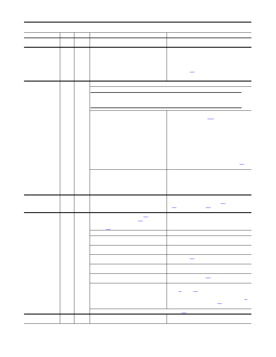
Port 1-5 Adapter
71…75
2
The communications card has a fault.
Check the DPI device event queue and corresponding fault
information for the device.
Port 1-5 DPI Loss
81…85
2
The DPI port stopped communicating.
1. Check the HIM connection.
2. If adapter was not intentionally disconnected, check the wiring
to the port. Replace the wiring, port expander, adapters, control
board or complete drive as required.
3. If an adapter was intentionally disconnected and the bit for that
adapter in Par
[Logic Mask] is set to “1”, this fault will occur.
To disable this fault, set the appropriate bit in [Logic Mask] for
the adapter to “0.”
Power Failure
3
2
Possible causes include:
There is a fault in the 24V control board supply - the voltage is
below the permitted value. In most cases the cause is in the
external I/O wiring.
• Pull the plug-in I/O terminal blocks out of the control circuit
board and reset the drive via
[Fault Clear]. If there are no
other faults, check the I/O wiring for a short-circuit including the
cable shielding.
• Check fuses F1 and F2 located on the Switching Power Supply
circuit board (frame A size drives only have one fuse - F1).
Replace as necessary.*
• Check varistor fuses F1, F2, and F3 on the Pulse Transformer or
Transient Noise Filter circuit boards for Frame C size drives.
Replace as necessary.*
• If this fault occurs again, an internal fault may be present.
Contact your Rockwell Automation sales office.
*Note: See Control Power Circuit Protection Fuses on page
fuse sizing information.
The incoming voltage to the control power terminals (U2, V2)
is too low due to:
• The AC input voltage is too low
• There are poor cable connections.
• The fuse(s) on the switching power supply circuit board
have blown.
• Verify AC input power level.
• Check all connections.
• Check and replace the fuse(s) if necessary.
Resolver Error
93
2
An error was detected with the resolver signal while it was
configured for use by the drive.
1. Verify the resolver wiring.
2. Verify the resolver configuration in Pars
[Reslvr Type Sel],
[Resolver Config].
3. Verify the resolver power supply.
Spd Fdbk Loss
91
1
The speed feedback device selected by Par
[Fdbk Device
Type] is indicating less than 5% of Par
[Max Feedback
Spd] while the measured armature voltage is greater than the
value of Par
[Spd FB Loss Lvl].
Possible causes include:
• The conductors of the feedback signal have been
interrupted.
Current from one or more of the feedback device wires is not
reaching the drive. Check the feedback device wiring.
• One or several encoder/resolver channels are missing
(conductor interruption, no power supply).
Check the encoder/resolver connections and power supply.
• The motor voltage is incorrect.
1. Verify that Par
[Rated Motor Volt] is set correctly
2. Tune the motor.
• The ramp rate is too fast for the connected load.
1. Reduce the load.
2. Reduce the ramp rate.
• Field Weakening is set incorrectly.
Verify the that the value of Par
[Fld Weaken Ratio] is set
properly.
The encoder or resolver configuration is incorrect.
1. For encoder feedback, verify the setting of DIP switch S20 (see
[Encoder Err Chk].
2. Verify that the connected encoder is capable of the input and
output voltage as determined by DIP switch S21 (see page
3. For resolver feedback, verify that Par
[Resolver Status] is not
indicating any errors.
Note: This fault condition can be configured to produce an alarm with Par
[Spd Loss Flt Cfg].
STune Aborted
62
2
The speed regulator auto tuning procedure has been stopped
by the user.
Informational only.
Fault Name
Number Type
(1)
Description/Possible Cause(s)
Action(s)
IMPORTANT
Remove power from the drive before removing the I/O terminal blocks and/or
fuses.