Rockwell Automation 20P PowerFlex Digital DC Drive User Manual
Page 166
166
Rockwell Automation Publication 20P-UM001I-EN-P - February 2013
Chapter 3
Programming and Parameters
UTILIT
Y
Diagno
st
ic
s
382
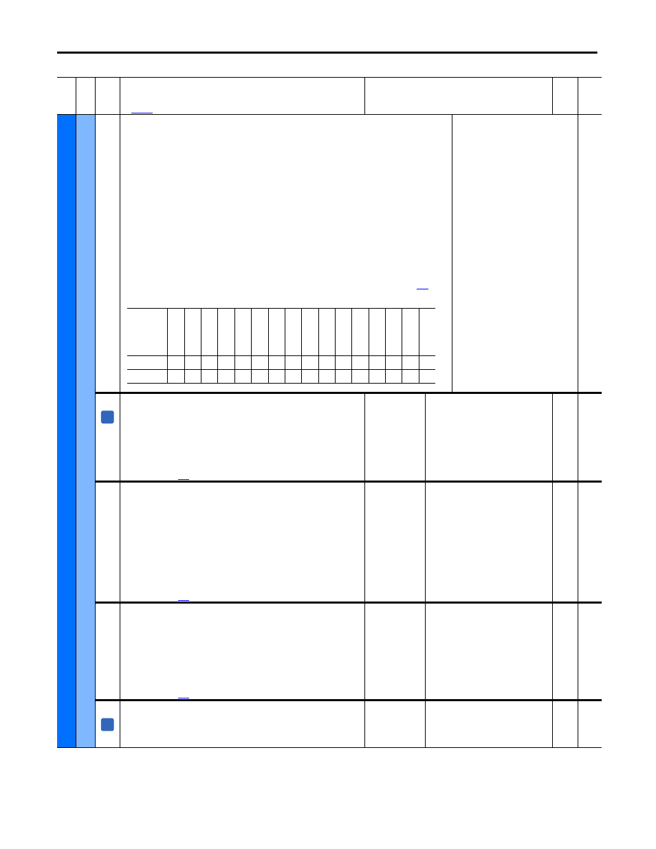
[Drive Status 2]
Present operating condition of the drive.
Bit 0 “Ready” - When set (= “1”), the drive is ready
Bit 1 “Active” - When set, the drive is active
Bit 2 “Running” - When set, the drive is running
Bit 3 “Jogging” - When set, the drive is being jogged
Bit 4 “Stopping” - When set, the drive is stopping
Bit 6 “Auto Tuning” - When set, the drive is auto tuning
Bit 7 “Forced Spd” - When set, the drive is in forced speed mode
Bit 8 “Speed Mode” - When set, the drive is in speed mode
Bit 9 “Torque Mode” - When set, the drive is in torque mode
Bit 10 “SpdRegPosLim” - When set, the Speed Regulator PI positive limit is active
Bit 11 “SpdRegNegLim” - When set, the Speed Regulator PI negative limit is active
Bit 12 “ArmAlphaTest” - When set, the Armature Alpha test is active
Bit 13 “FldAlphaTest” - When set, the Field Alpha test is active
Notes: Added bits 7…13 for firmware version 3.001. See Torque Mode Selection Status Bits on page
for
more information.
Read Only
393
[Speed Threshold]
Indicates if the drive is above or below the threshold speed specified in parameters
101 [Speed Thresh Pos] (clockwise rotation) and 102 [Speed Thresh Neg] (counter-
clockwise rotation).
• “0 Above Thresh” = The speed has exceeded the set speed threshold.
• “1 Below Thresh” = The speed has not exceeded the set speed threshold.
Notes: This parameter can be assigned to a digital output. See Speed Threshold
Indicators on page
for more information.
Default:
Min/Max:
Read Only
0 / 1
16-bit
Int
101,
102,
103
394
[At Speed]
Indicates whether or not the current speed of the drive corresponds to the speed
reference (specified in Par 118 [Speed Reg In]) before the speed regulator and the
ramp reference (if enabled) are applied. The speed above and below the speed
reference at which [At Speed] will indicate “1 Equal” is set in Par 104 [At Speed
Error].
• “0 Not Equal” - The drive is not working at the set speed reference.
• “1 Equal” - The drive is working at the set speed reference.
Notes: This parameter can be assigned to a digital output. It also corresponds to
the “At Speed” indication on the Status Line of the HIM. See Speed Threshold
Indicators on page
for more information.
Default:
Min/Max:
Read Only
0 / 1
16-bit
Int
104,
105
395
[At Zero Speed]
Indicates whether or not the actual speed of the motor is below the zero speed
threshold as specified in Par 107 [Speed Zero Level].
• “0 Equal” - The actual speed is below the value of Par 107 [Speed Zero Level]
and Par 108 [Speed Zero Delay] has timed out.
• “1 Not Equal” - The actual speed is above the value of Par 107 [Speed Zero
Level].
Notes: This parameter can be assigned to a digital output. See Speed Threshold
Indicators on page
for more information.
Default:
Min/Max:
Read Only
0 / 1
16-bit
Int
107,
108
396
[MOP Inc Active]
Indicates whether or not the drive is accelerating using the preselected ramp.
• 0 “No Accel” = the drive is not accelerating using a preselected ramp
• 1 “Accel” = the drive is accelerating using a preselected ramp
Default:
Min/Max:
Read Only
0 / 1
16-bit
Int
Fil
e
Gr
oup
No
.
Parameter Name & Description
See
page 110
for symbol descriptions
Values
Da
ta
T
yp
e
Rela
ted
Options
Res
er
ved
Res
er
ved
Fl
dA
lp
ha
Te
st
Ar
m
Al
ph
aT
es
t
SpdRegN
egLim
SpdRegP
osLim
To
rq
ue
Mode
Speed
Mode
Fo
rc
ed
S
pd
Auto
T
un
in
g
Cu
rr Limit
Stop
pi
ng
Jo
gg
ing
Ru
nni
ng
Ac
tiv
e
Ready
Default
x
x
0
0
0
0
0
0
0
0
0
0
0
0
0
1
Bit
15
14
13
12
11
10
9
8
7
6
5
4
3
2
1
0
A
A