Rockwell Automation 20P PowerFlex Digital DC Drive User Manual
Page 188
188
Rockwell Automation Publication 20P-UM001I-EN-P - February 2013
Chapter 3
Programming and Parameters
INPUT
/ OU
TPU
T
D
igi
ta
l O
u
tpu
ts
581
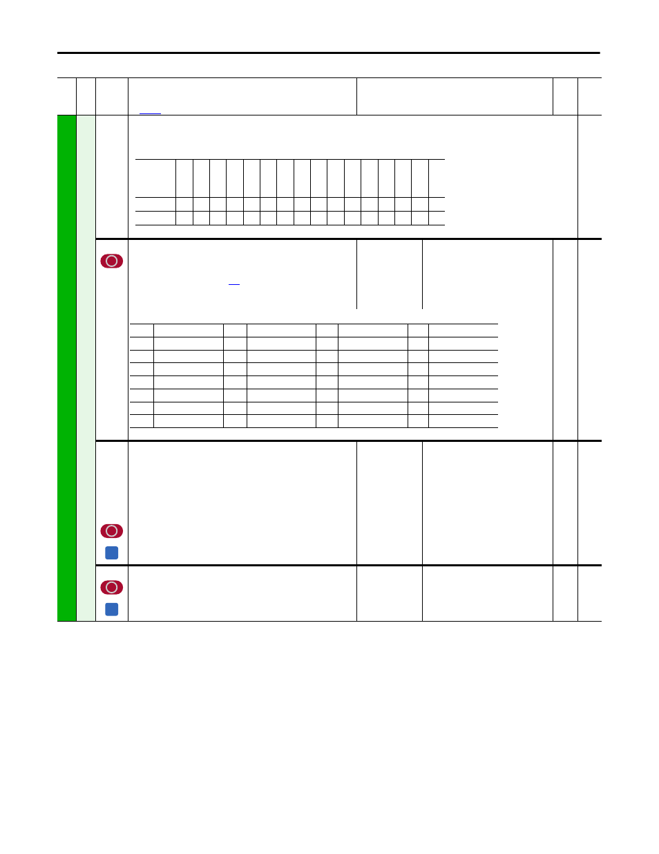
[Dig Out Status]
Status of the standard digital outputs and relay outputs on the drive and on the optional I/O
Expansion circuit board (if present).
Read Only
629
[Relay Out 2 Sel]
Selects the source of the value that drives the N.O. relay between the
terminals 75 and 76.
See “Option Definitions” on page
.
Note: Option 16 “Encoder Err” was changed for firmware version
v5.002.Options:
Default:
5 =
“Ready”
16-bit
Int
1267
1268
1269
1270
1271
1272
1273
1274
[Inversion Out 1]
[Inversion Out 2]
[Inversion Out 3]
[Inversion Out 4]
[Inversion Out 5]
[Inversion Out 6]
[Inversion Out 7]
[Inversion Out 8]
Reverses the digital output signal.
Default:
Options:
0 =
0 =
1 =
“Disabled”
“Disabled”
“Enabled”
16-bit
Int
1275
[Inversion Relay2]
Inverts the signal for Relay Output 2.
Default:
Options:
0 =
0 =
1 =
“Disabled”
“Disabled”
“Enabled”
16-bit
Int
Fil
e
Gr
oup
No
.
Parameter Name & Description
See
page 110
for symbol descriptions
Values
Da
ta
T
yp
e
Rela
ted
Options
Re
la
y O
ut2
Re
la
y O
ut1
Re
ser
ve
d
Re
ser
ve
d
Re
ser
ve
d
Re
ser
ve
d
Re
ser
ve
d
Re
ser
ve
d
Di
gi
ta
l Ou
t8
Di
gi
ta
l Ou
t7
Di
gi
ta
l Ou
t6
Di
gi
ta
l Ou
t5
Di
gi
ta
l Ou
t4
Di
gi
ta
l Ou
t3
Di
gi
ta
l Ou
t2
Di
gi
ta
l Ou
t1
Default
0
0
x
x
x
x
x
x
0
0
0
0
0
0
0
0
Bit
15
14
13
12
11
10
9
8
7
6
5
4
3
2
1
0
0 =
“Not Used” (Off)
8 =
“Spd Limited”
16 = “Spd Fdbk Err”
24 = “ContactDB”
1 =
“Spd Zero Thr”
9 =
“Fault”
17 = “Diam Calc”
25 = “Contactor”
2 =
“Spd Thresh”
10 = “Power Loss”
18 = “Input1 Cmp”
26 = “Alarm”
3 =
“At Speed”
11 =
“UserDefinedA”
19 = “Diam Reached”
27 = “Running”
4 =
“CurrentLimit”
12 =
“UserDefinedB”
20 = “Speed Match”
28 = “Jogging”
5 =
“Ready”
13 = “Stop Control”
21 = “Accelerating”
29 = “Active”
6 =
“Ramp Pos”
14 =
“Field Loss”
22 = “Decelerating”
7 =
“Ramp Neg”
15 =
“Spd Fbk Loss”
23 = “Brake Cmd”
A
A