Appendix f, What this option board provides, I/o expansion board wiring – Rockwell Automation 20P PowerFlex Digital DC Drive User Manual
Page 343: Optional analog and digital i/o, Expansion circuit board, Appendix
Rockwell Automation Publication 20P-UM001I-EN-P - February 2013
343
Appendix
F
Optional Analog and Digital I/O Expansion
Circuit Board
What This Option Board
Provides
The optional I/O Expansion circuit board
(1)
is mounted on the control board of
the drive and provides these additional I/O signals:
•
Four Digital Inputs
•
Four Digital Outputs
•
Two Analog Outputs
This circuit board is catalog number 20P-S5V62.
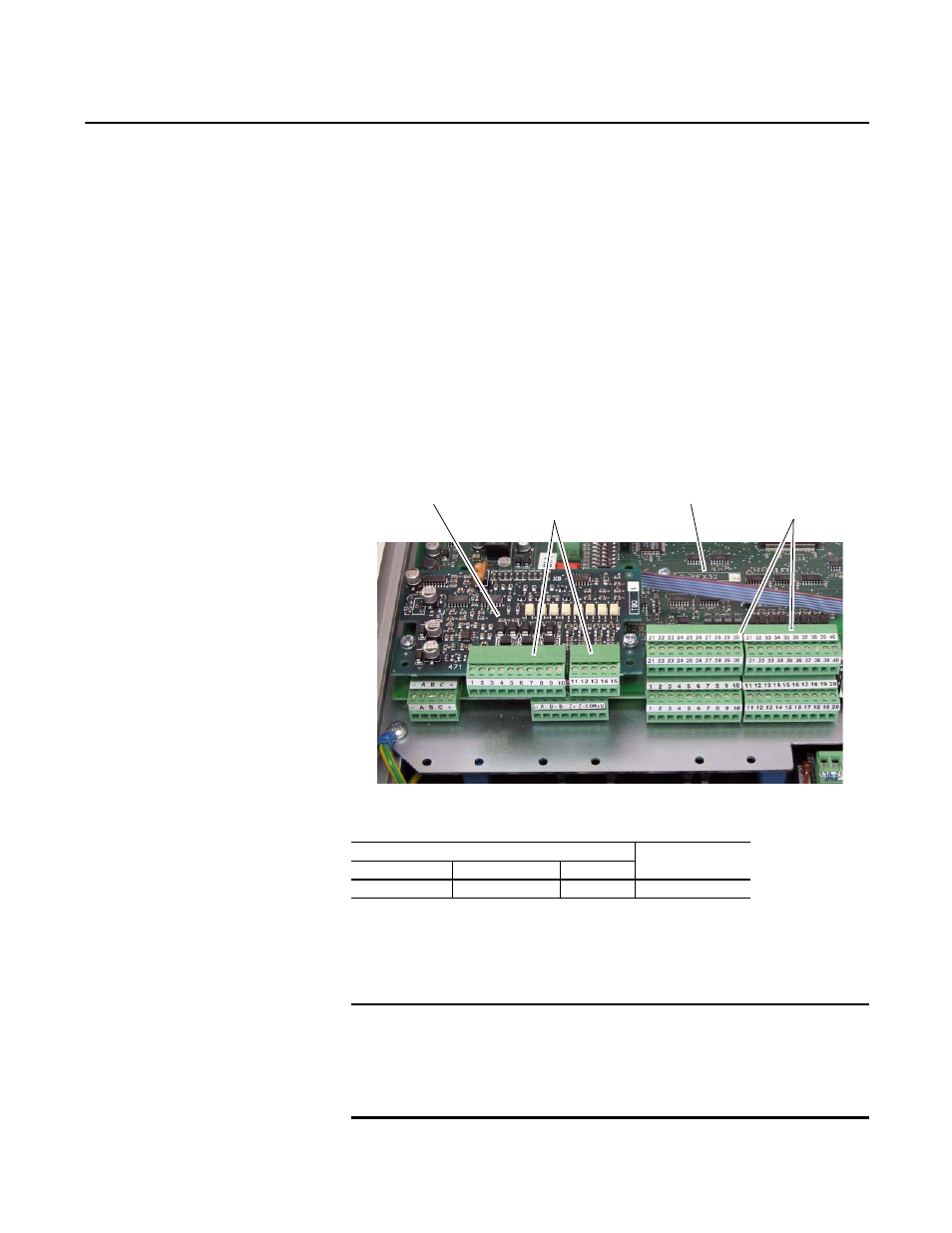
Figure 95 - I/O Expansion Board Mounting Location
I/O Expansion Board Wiring
Table 90 - Recommended Signal Wire Size
A 75 x 2.5 x 0.4 mm (3.0 x 0.1 x 0.02 in.) flathead screwdriver is recommended
for connecting wire to the terminal block inputs. Strip the ends of the cables to a
length of 6.5 mm (0.26 in.).
(1) The Analog and Digital I/O Expansion circuit board is not factory installed.
I/O Expansion Board
Control Board
Standard Drive I/O
Terminal Blocks
I/O Expansion Board
Terminal Blocks
Wire Type and Size
Tightening Torque
N
•
m (lb
•
in)
Flexible (mm
2
)
multi-core (mm
2
)
AWG
0.14…1.5
0.14…1.5
28…16
0.4 (3.5)
IMPORTANT
To improve the noise immunity it is recommended that you connect the
common of the outputs (terminals 2, 4, 5 and 15 of the I/O Expansion board)
with the ground (terminal 10 or 20) on the standard I/O terminal blocks on the
control board. If this is not possible, these terminals must be grounded by
means of a 0.1 mf/250V capacitor.