Rockwell Automation 20P PowerFlex Digital DC Drive User Manual
Page 177
Rockwell Automation Publication 20P-UM001I-EN-P - February 2013
177
Programming and Parameters
Chapter 3
CO
MMUNIC
ATIONS
Masks
&
O
w
ne
rs 631
[Decel Mask]
Controls which adapters can select the deceleration ramp rate (Pars 662
[Decel Time 1] and 32 [Decel Time 2]) of the drive.
32,
662
Da
ta
Li
n
ks
610
611
[Data In A1] – Link A Word 1
[Data In A2] – Link A Word 2
Parameter number whose value will be written from a communications
device data table. The number will not be updated until the drive is
stopped.
See your communications option manual for datalink information.
Default:
Min/Max:
0 (0 = “Disabled”)
0 / 1410
16-bit
Int
612
613
[Data In B1] – Link B Word 1
[Data In B2] – Link B Word 2
See [Data In A1] – Link A Word 1.
16-bit
Int
614
615
[Data In C1] – Link C Word 1
[Data In C2] – Link C Word 2
See [Data In A1] – Link A Word 1.
16-bit
Int
616
617
[Data In D1] – Link D Word 1
[Data In D2] – Link D Word 2
See [Data In A1] – Link A Word 1.
16-bit
Int
618
619
[Data Out A1] – Link A Word 1
[Data Out A2] – Link A Word 2
Parameter number whose value will be written to a communications device
data table.
Default:
Min/Max:
0 (0 = “Disabled”)
0 / 1410
16-bit
Int
620
621
[Data Out B1] – Link B Word 1
[Data Out B2] – Link B Word 2
See [Data Out A1] – Link A Word 1.
16-bit
Int
622
623
[Data Out C1] – Link C Word 1
[Data Out C2] – Link C Word 2
See [Data Out A1] – Link A Word 1.
16-bit
Int
624
625
[Data Out D1] – Link D Word 1
[Data Out D2] – Link D Word 2
See [Data Out A1] – Link A Word 1.
16-bit
Int
1319 [Data In Val Sel]
Selects the Datalink parameter register to display in Par 1320 [Data In Sel
Data].
Default:
Min/Max:
610
610 / 617
16-bit
Int
1320
1320 [Data In SelData]
Displays the value selected in Par 1319 [Data In Val Sel].
Default:
Min/Max:
Read Only
0 / 2
31
32-bit
Int
1319
Secur
ity
591
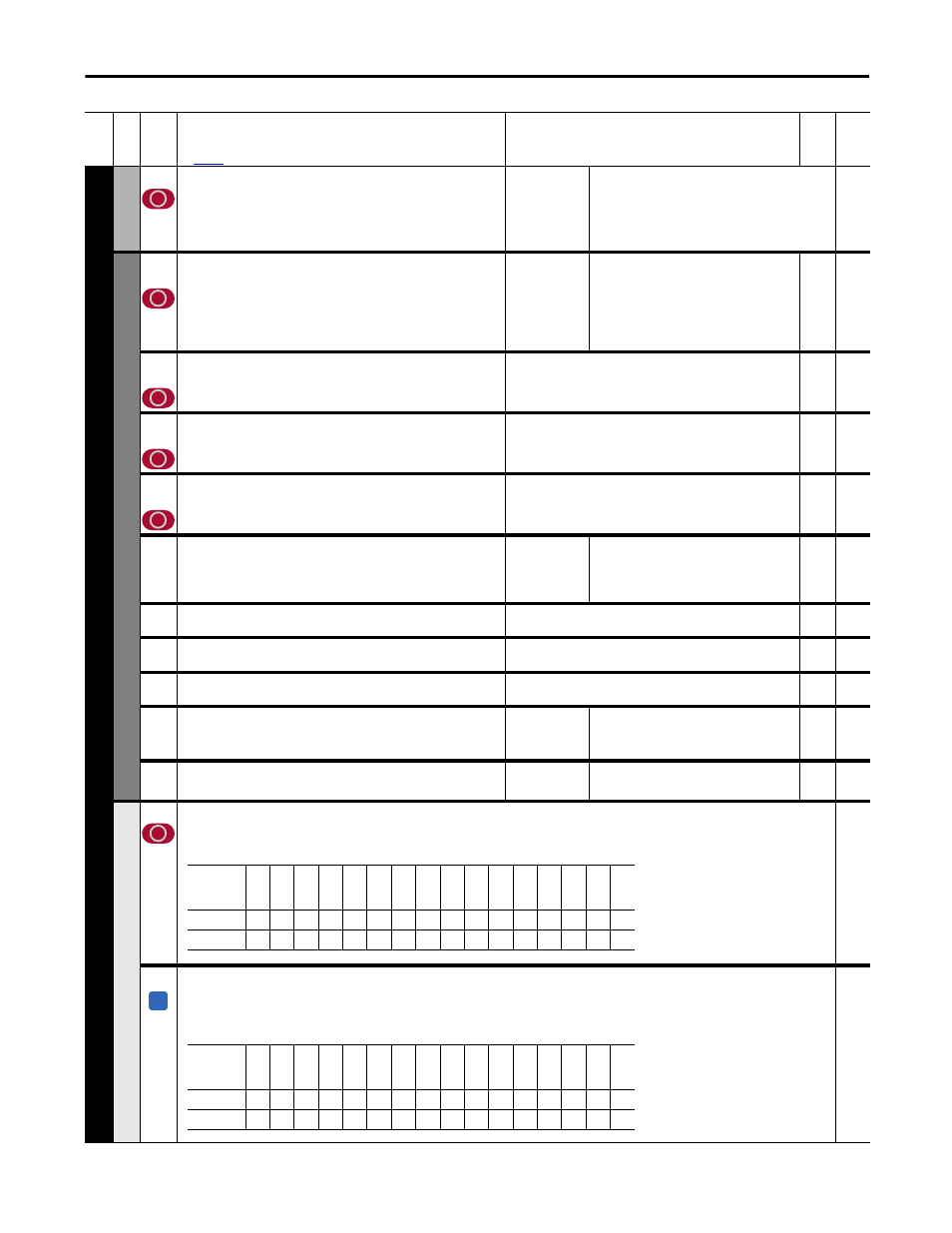
[Logic Mask]
Determines which ports can control the drive. If the bit for a port is set to “0,” the port will have no control functions except for stop. 0 = Control Masked, 1
= Control Permitted, x = Reserved.
1376 [Logic Mask Act]
Indicates the status of the logic mask for the DPI ports. When bit 15 is set, network security is
controlling the logic mask instead of Par 591 [Logic Mask]. 0 = Control Masked, 1 = Control
Permitted, x = Reserved.
Read Only
591
Fil
e
Gr
oup
No
.
Parameter Name & Description
See
page 110
for symbol descriptions
Values
Da
ta
T
yp
e
Rela
ted
Options
Re
se
rv
ed
Re
se
rv
ed
Re
se
rv
ed
Re
se
rv
ed
Re
se
rv
ed
Re
se
rv
ed
Re
se
rv
ed
Re
se
rv
ed
Re
se
rv
ed
Re
se
rv
ed
DPI P
or
t 5
DPI P
or
t 4
DPI P
or
t 3
DPI P
or
t 2
DPI P
or
t 1
Di
gi
ta
l I
n
Default
x
x
x
x
x
x
x
x
x
x
1
1
1
1
1
1
Bit
15
14
13
12
11
10
9
8
7
6
5
4
3
2
1
0
A
Options
Se
cu
rit
y
Rese
rv
ed
Rese
rv
ed
Rese
rv
ed
Rese
rv
ed
Rese
rv
ed
Rese
rv
ed
Rese
rv
ed
Rese
rv
ed
Rese
rv
ed
DPI P
or
t 5
DPI P
or
t 4
DPI P
or
t 3
DPI P
or
t 2
DPI P
or
t 1
Dig
ital
In
Default
0
x
x
x
x
x
x
x
x
x
1
1
1
1
1
1
Bit
15
14
13
12
11
10
9
8
7
6
5
4
3
2
1
0