Armature converter connections – Rockwell Automation 20P PowerFlex Digital DC Drive User Manual
Page 50
50
Rockwell Automation Publication 20P-UM001I-EN-P - February 2013
Chapter 1
Installation and Wiring
Armature Converter Connections
Table 10 - Armature and Safety Ground (PE) Terminal Specifications
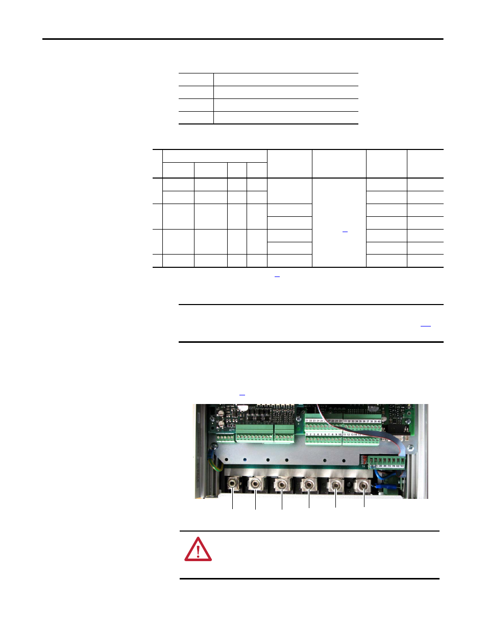
Figure 22 - Frame A Armature Converter Terminal Locations
Terminals
Description
U, V, W
Three phase AC input to the armature converter
C, D
DC output to the motor armature
PE
Safety ground
Fram
e
Drive Current Rating Code
(1)
Terminals
Wire Size and Type
Terminal Bolt
Size (mm)
Tightening
Torque
N
•m (lb•in)
230V
460V
575
690
A
7P0…055
4P1…052
–
–
U, V, W, C, D, PE
page
5
6 (53)
073…110
073…129
–
–
Terminal Block
12 (106)
B
All
All
All
–
U, V, W, C, D
10
25 (221)
PE
8
15 (132.75)
C
All
All
All
All
U, V, W, C, D
10
25 (221)
PE
8
15 (132.75)
D
All
All
All
All
U, V, W, C, D, PE
12
45 (398.2)
(1) See Standard Drive Catalog Number Explanation on page
, positions 8, 9 and 10 for corresponding drive HP rating, armature amp rating and
field amp rating.
IMPORTANT
Certain frame D drives require the use of a terminal adapter kit(s) for terminals
U, V, W, C and D. See Terminal Adapter Kits for Frame D Drives on page
for
details.
U
C
V
D
W
PE
Front View
ATTENTION: Do not operate the drive with the power terminal cover removed.
Operating the drive with the power terminal cover removed may result in a
hazardous condition that could cause personal injury and/or equipment
damage.
Note: Front view of drive shown with bottom protective and power terminal covers removed. See Removing the
Drive Covers on page
for information on removing the drive covers.