Rockwell Automation 20P PowerFlex Digital DC Drive User Manual
Page 171
Rockwell Automation Publication 20P-UM001I-EN-P - February 2013
171
Programming and Parameters
Chapter 3
UTILIT
Y
Al
arms
365
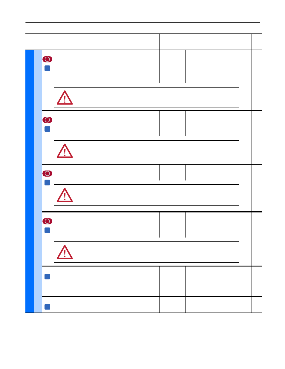
[OverTemp Flt Cfg]
Determines the response of the drive to a motor over temperature condition (F16
“Motor Over Temp”).
Notes: See Chapter 4 for a list of alarm and fault descriptions. Option 3 was
changed from “Quick Stop” for firmware version 2.001.
Default:
Options:
2 =
0 =
1 =
2 =
3 =
4 =
5 =
“Fault”
“Ignore”
“Alarm”
“Fault”
“Fast Stop”
“Normal Stop”
“CurrLim Stop”
16-bit
Int
473
[FldLoss Flt Cfg]
Determines the response of the drive to a field loss condition (F6 “Fld Current
Loss”). If Par 497 [Field Reg Enable] is set to 0 “Disabled”, this parameter should be
set to 0 “Ignore”.
Note: See Chapter 4 for a list of alarm and fault descriptions.
Default:
Options:
2 =
0 =
1 =
2 =
“Fault”
“Ignore”
“Alarm”
“Fault”
16-bit
Int
497
478
[Spd Loss Flt Cfg]
Determines the response of the drive to a speed feedback loss condition.
Note: See Chapter 4 for a list of fault and alarm descriptions.
Default:
Options:
2 =
1 =
2 =
“Fault”
“Alarm”
“Fault”
16-bit
Int
458
479
[MtrOvrld Flt Cfg]
Determines the response of the drive to a motor overload condition (F7 “Motor
Overload”).
Notes: See Chapter 4 for a list of fault and alarm descriptions. This parameter was
added for firmware version 3.001.
Default:
Options:
2 =
0 =
1 =
2 =
“Fault”
“Ignore”
“Alarm”
“Fault”
16-bit
Int
376,
1290
481
[UnderVolt Thresh]
The AC input voltage level below which an undervoltage fault (F4 “AC
Undervoltage”) will be detected. A typical value is 85% of the nominal AC line
voltage (Par 466 [AC Line Voltage]). This fault can only occur while the drive is
running.
Note: See Chapter 4 for a list of fault descriptions.
Default:
Min/Max:
Units:
230
0 / 1000
Vac
16-bit
Int
584
[OverCurrent Thr]
Value at which an overcurrent condition (F13 “Overcurrent”) will be detected.
Note: See Chapter 4 for a list of fault descriptions.
Default:
Min/Max:
Units:
175
0 / 250
%
16-bit
Int
Fil
e
Gr
oup
No
.
Parameter Name & Description
See
page 110
for symbol descriptions
Values
Da
ta
T
yp
e
Rela
ted
A
ATTENTION: Setting this parameter to 0 “Ignore” or 1 “Alarm”, could result in motor and/or equipment damage. If set to
“Ignore” or “Alarm”, it is strongly recommended that an external means of protecting against this condition be provided.
A
ATTENTION: Setting this parameter to 0 “Ignore” or 1 “Alarm”, could result in motor and/or equipment damage. If set to
“Ignore” or “Alarm”, it is strongly recommended that an external means of protecting against this condition be provided.
A
ATTENTION: Par 478 [Spd Loss Flt Cfg] must be set to 1 “Fault” if Par 458 [SpdReg FB Bypass] is set to 0 “Disabled”. Failure
to observe this precaution could result in high motor speeds, equipment damage, and/or bodily injury if a “Spd Fdbk Loss”
alarm condition were encountered.
A
ATTENTION: Setting Par 479 [MtrOvrld Flt Cfg] to 0 “Ignore” or 1 “Alarm”, could result in motor and/or equipment damage.
Ensure that the motor is properly sized for the application and that a separate device is installed that monitors for and
signals a motor overload condition.
A
A