Mechanical installation, Cutout in the control cabinet – Lenze E82xVxxxKxxxxx User Manual
Page 91
Mechanical installation
Standard devices with a power of 55 kW
Thermally separated mounting (push−through technique)
l
91
EDS82EV903−3.0
5.6.2
Thermally separated mounting (push−through technique)
For this mounting variant you require the controller type E82DV...
)
Note!
Before assembling the controller, please read the documentation for the
components connected on the supply side (mains choke, filter).
)
Note!
For thermally separated mounting the fan module has to be rotated by 180° so
that the controller fits into the mounting cutout. (
¶ 92)
d2
d2
d2
d
b
g
e2
a
d1
h
h
e3
c2
c3
c4
e
e1
L
a1
d3
b1
c1
9300vec174
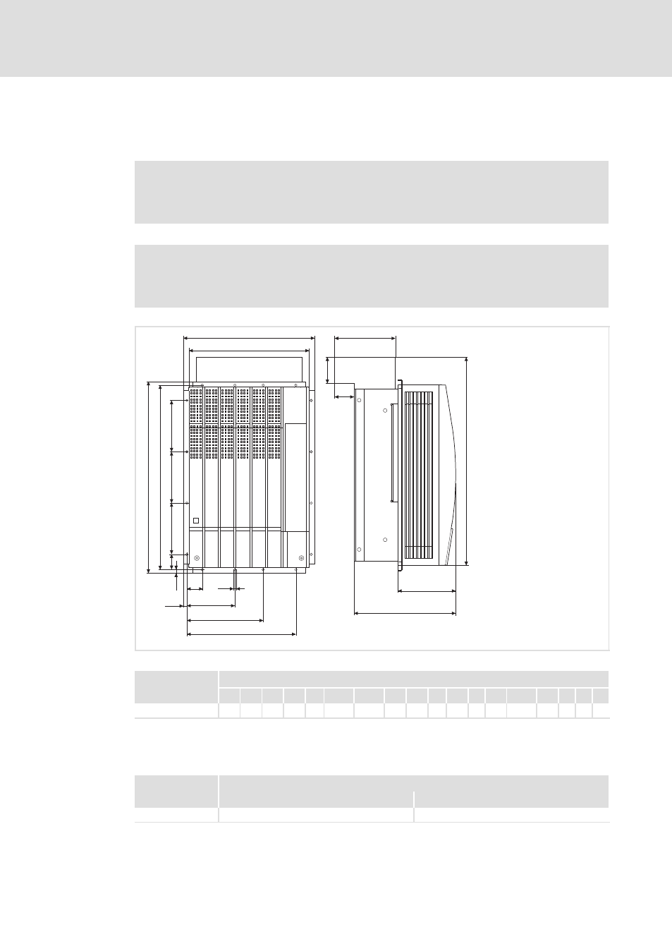
Fig. 5−25
Dimensions for thermally separated mounting 55 kW
Dimensions [mm]
8200 vector
a
a1
b
b1
c1
c2
c3
c4
d
d1 d2 d3 e
1)
E1
e2 e3 g
h
E82DV553K4B
373 340 543 591 45 137.5 217.5 310 525 45 145 81 285 163.5 185 66 7
9
1)
If the function module is attached: observe mounting clearance and cable bending radius. The terminals of function
modules in PT design protrude above the housing by 8 mm.
Cutout in the control cabinet
Dimensions [mm]
8200 vector
Width
Height
E82DV553K4B
320
492