5 motor connection, Motor connection, Electrical installation – Lenze E82xVxxxKxxxxx User Manual
Page 154
Electrical installation
Standard devices in the power range of 55 kW
Motor connection
l
154
EDS82EV903 EN 3.0
6.7.5
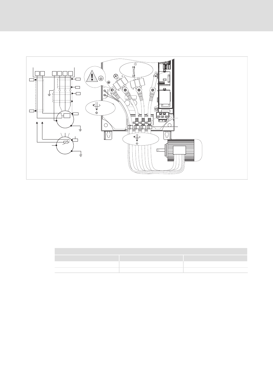
Motor connection
U
V
W
PE
T1
T2
U, V, W,
PE
15 Nm
132 lb-in
M 8
PE
T1
T2
2,5 Nm
22.1 lb-in
PE
PE
M
3~
M
3~
PTC
PE
PES
PE
U
V
W
T1
T2
J>
PES
PES
PES
PES
PES
PES
1
0
3 Nm/26.5 lb-in
M5 × 12
8200vec286
Fig. 6−23
Motor connection 45 ... 55 kW
0
Place the shield of the motor cables with shield clamp and M5 × 12 mm screws onto the shield
sheet.
1
Strain relief with cable binders.
Use low−capacitance motor cables! (Core/core
£ 190 pF/m, core shield £ 320 pF/m)
The shorter the motor cable, the better the drive behaviour!
PES
HF shield termination by PE connection through shield clamp.
T1,
T2
Terminals of motor temperature monitoring with PTC thermistor or thermal contact (NC
contact).
Lay a separate cable (shielded) to X2/T1 and X2/T2 for motor temperature monitoring.
Activate motor temperature monitoring with C0119 (e.g. C0119 = 1)!
Lay the control and mains cables separately from the motor cable!
Cable cross−sections U, V, W, PE
8200 vector
mm
2
AWG
СССССССССС
СССССССССС
E82xV453K4B
СССССССССС
СССССССССС
50
1
СССССССССС
СССССССССС
E82xV553K4B
СССССССССС
СССССССССС
50
0