Dc−bus operation – Lenze E82xVxxxKxxxxx User Manual
Page 462
DC−bus operation
Conditions for trouble−free DC−bus operation
Mains connection
l
462
EDS82EV903−3.0
Controller protection
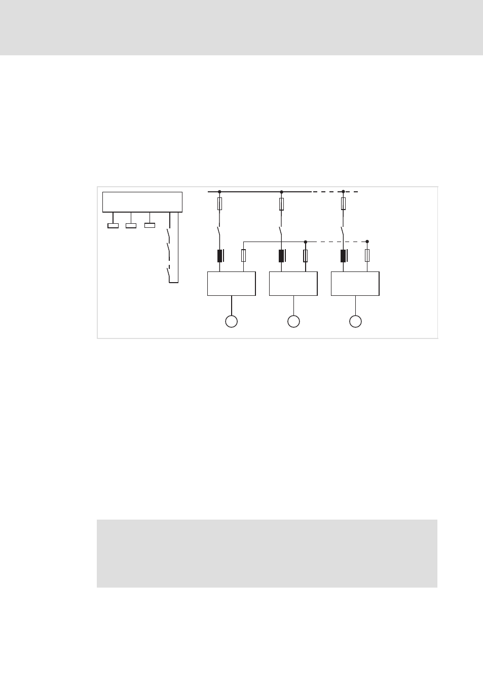
Please ensure that all controllers in the DC−bus system are connected simultaneously to the mains
supply.
Starting conditions
Use a central mains contactor (
¶ 480)
Decentralised switching of the mains supply is possible if the connection of the individual
contactors is monitored (feedback to PLC) and the contactors are switched with the same
cycle.
A1
A2
An
F4, F5
F1 ... F3
AC
M
M
M
K1
DC
K2
Kn
PLC
K1
K2
Kn
K2
K1
K2
Kn
Z1
Z2
Zn
8200vec650
Fig. 12−1
Decentralised switching of the mains supply in network operation
A1 ... An
Controller 1 ... controller n
F1 ... F3
Mains fuses
F4 ... F5
Fuses on DC level
Z1 ... Zn
Mains choke
K1 ... Kn
Mains contactors
Adapt to the mains voltage
Select the same value for the switching threshold of the brake module / brake chopper for
all controllers in the DC−bus system:
93xx: C0173
8200 vector: C0174
Mains phase failure detection with decentralised supply
Monitor the mains supply for every controller because all active mains input circuits of the
system may be overloaded in the event of a mains failure.
)
Note!
Switch off the entire drive system in the event of a mains failure or mains
phase failure (
¶ 480)
Use thermal overcurrent releases for the mains failure detection and reports
(bimetal relays) which are connected downstream of the mains fuses.