6 connection relay outputs k1 and k2, Connection relay outputs k1 and k2, Electrical installation – Lenze E82xVxxxKxxxxx User Manual
Page 147
Electrical installation
Standard devices in the power range 15 ... 30 kW
Connection relay outputs K1 and K2
l
147
EDS82EV903 EN 3.0
6.6.6
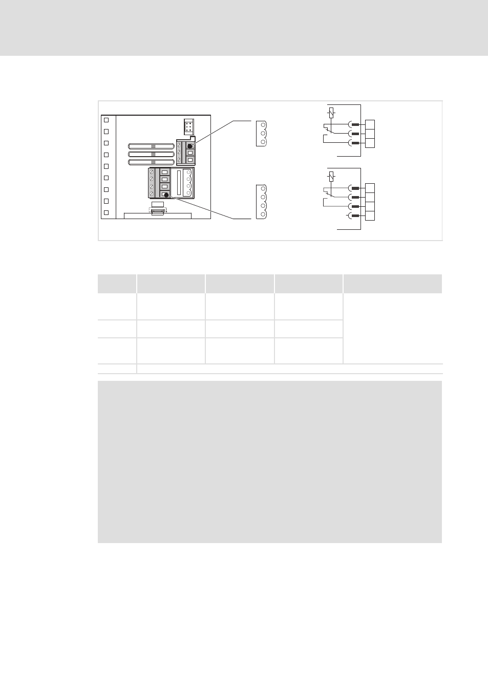
Connection relay outputs K1 and K2
K14
K1
K2
K12
K11
K24
nc
K11
K21
K12
K22
X1.2
X1.3
K14
K24
nc
K22
K21
8200vec261
Fig. 6−20
Relay connections K1 and K2
Relay K1
Function
Relay position
switched
Message
(Lenze setting)
Technical data
X1.2/K11
Relay output
normally−closed
contact
opened
TRIP
250 VAC/3 A
DC 24 V/2 A ... DC 240 V/0.22 A
X1.2/K12
Relay mid−position
contact
X1.2/K14
Relay output
normally−open
contact
closed
TRIP
PES
HF shield termination by PE connection through shield clamp
)
Note!
ƒ
Switching of control signals:
– Use shielded cables
– HF shield termination by PE connection
– The minimum load for switching the signals through correctly is 12 V and
5 mA. Both values have to be exceeded at the same time.
ƒ
Switching of mains potentials:
– Unshielded cables are sufficient
ƒ
For the protection of the relay contacts a corresponding suppressor circuit is
absolutely required for an inductive or a capacitive load!
ƒ
The service life of the relay depends on the type of load (ohmic, inductive or
capacitive) and the value of the switching capacity.
ƒ
The message that is output can be changed in code C0008 or C0415/1.