2 mains connection, Mains connection, Dc−bus operation – Lenze E82xVxxxKxxxxx User Manual
Page 461
DC−bus operation
Conditions for trouble−free DC−bus operation
Possible combinations of Lenze controllers in a network of several drives
l
461
EDS82EV903−3.0
12.3.1
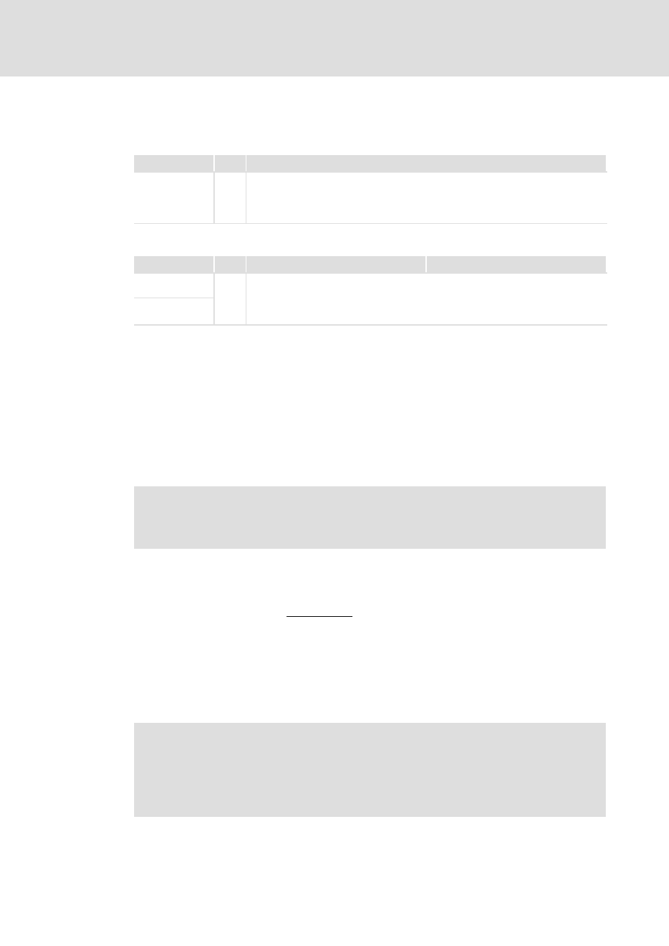
Possible combinations of Lenze controllers in a network of several drives
Combinations in the 230 V mains
Type
Data
E82xVxxxK2C
E82xVxxxK2C
3 / PE / AC / 100 V − 0 % ... 264 V + 0%
45 Hz − 0 % ... 65 Hz + 0 %
DC 140 V ... 370 V
DC 380 V
Combinations in the 400 V mains
Type
Data
E82xVxxxK4x
93xx
E82xVxxxK4x
3 / PE / AC / 320 V − 0 % ... 440 V + 0 %
45 Hz − 0 % ... 65 Hz + 0 %
93xx
DC 460 V ... 620 V
DC 725 V
max. permissible range mains voltage
permissible range DC−bus voltage
switching threshold of the braking unit
12.3.2
Mains connection
Cable protection and cable cross−section
Dimension the mains fuses and the cable cross−section of the mains cables for the mains
current resulting from the maximum supply power P
DC100%
. Additional basic conditions
such as local regulations, temperatures, etc. must also be observed. (
¶ 467)
)
Note!
An asymmetrical DC−bus system may require higher dimensioning by factor
1.35 ... 1.5.
Mains current
Rule of thumb for the mains current in a DC−bus system:
I
Netz
[A] [
P
DC100%
[W]
1.6 @ U
Netz
[V]
Mains chokes. EMC
The application of mains chokes limits and proportionally allots the current and the power
of the mains input circuits of the controllers (depending on their performance).
Only use mains chokes that are specified for DC−bus operation. (
¶ 465)
)
Note!
Please observe that the DC−bus operation may require different mains chokes,
mains fuses and cable cross−sections than the individual operation.
Compliance with the EMC Directive may not be ensured. Check the application
of central interference suppression (collective filter) in the AC supply.