Application examples – Lenze E82xVxxxKxxxxx User Manual
Page 509
Application examples
Speed control
l
509
EDS82EV903 EN 3.0
Speed sensor requirements
)
Note!
You can use every speed sensor which meets the level and scanning ratio
requirements.
ƒ
The maximum frequency of inductive sensors generally ranges from 1 ... 6 kHz
depending on the type.
ƒ
At the detection point, the number of attenuation cams per revolution must ensure
an output frequency of the sensor as high as possible.
ƒ
The control dynamics will be sufficient if the output frequency (f
act
) is > 0.5 kHz at
rated speed.
ƒ
If the current consumption of the sensor is not higher than the value permitted at
X3/20, a three−wire sensor can be directly connected to the controller.
Output frequency calculation
f
ist+
z @ n
60
z = number of cams per revolution
n = speed at the detection point [rpm]
f
act
= output frequency of the sensor in [Hz]
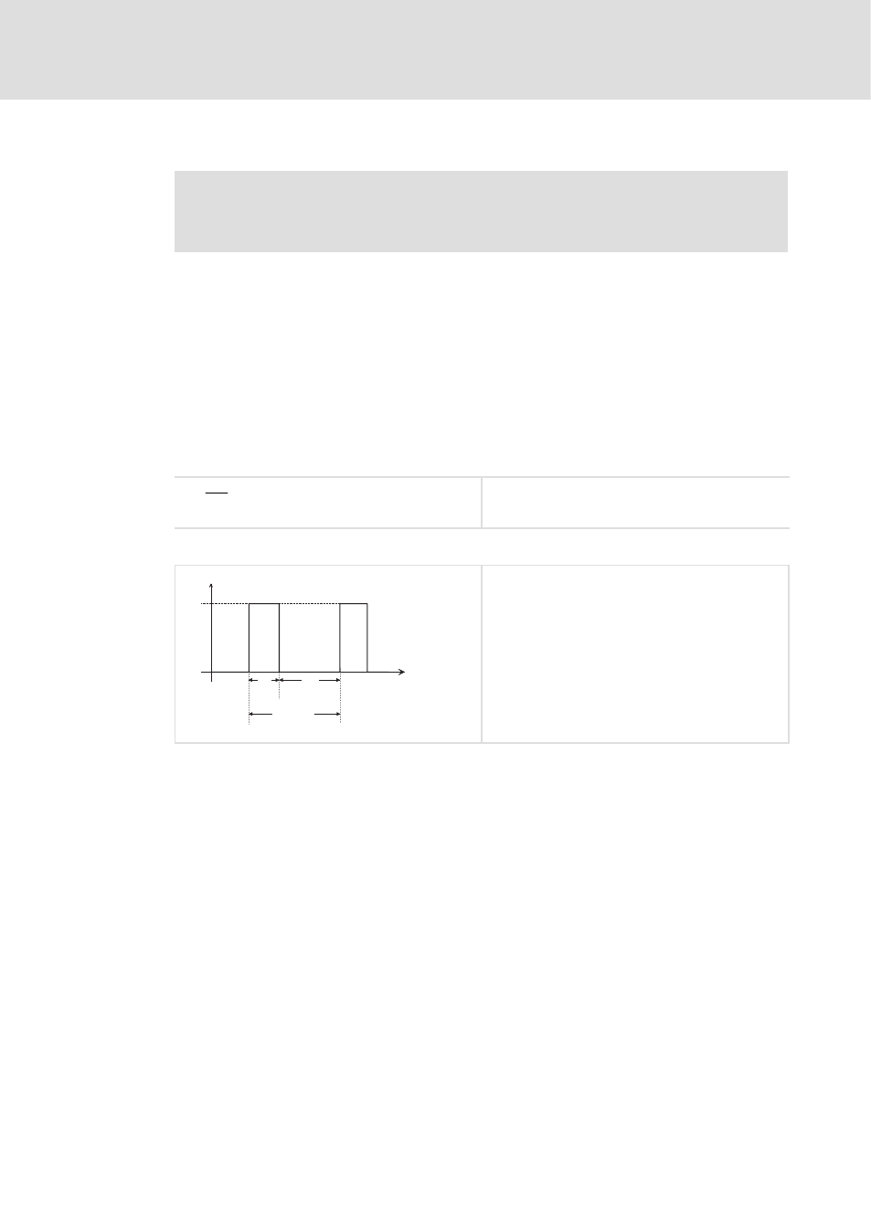
Permissible pulse shape at X3/E1
T ³ 1 0 0 m s
T e
T a
1 5 V
U
E 1
t
0
0
l
T
e
= on (HIGH)
l
T
a
= off (LOW)
Permissible level range:
l
LOW: 0 ... +3 V
l
HIGH: +12 ... +30 V
Permissible range of the scanning ratio
l
T
e
: T
a
= 1 : 1 until T
e
: T
a
= 1 : 5