Mechanical installation – Lenze E82xVxxxKxxxxx User Manual
Page 68
Mechanical installation
Standard devices in a power range from 0.25 ... 2.2 kW
Mounting in "cold plate" technique
l
68
EDS82EV903−3.0
8200 vector 0.25 ... 2.2 kW
M6
4 Nm
35 lbin
c
f
a1
b1
b
a
d
c1
b2
e
8200vec029
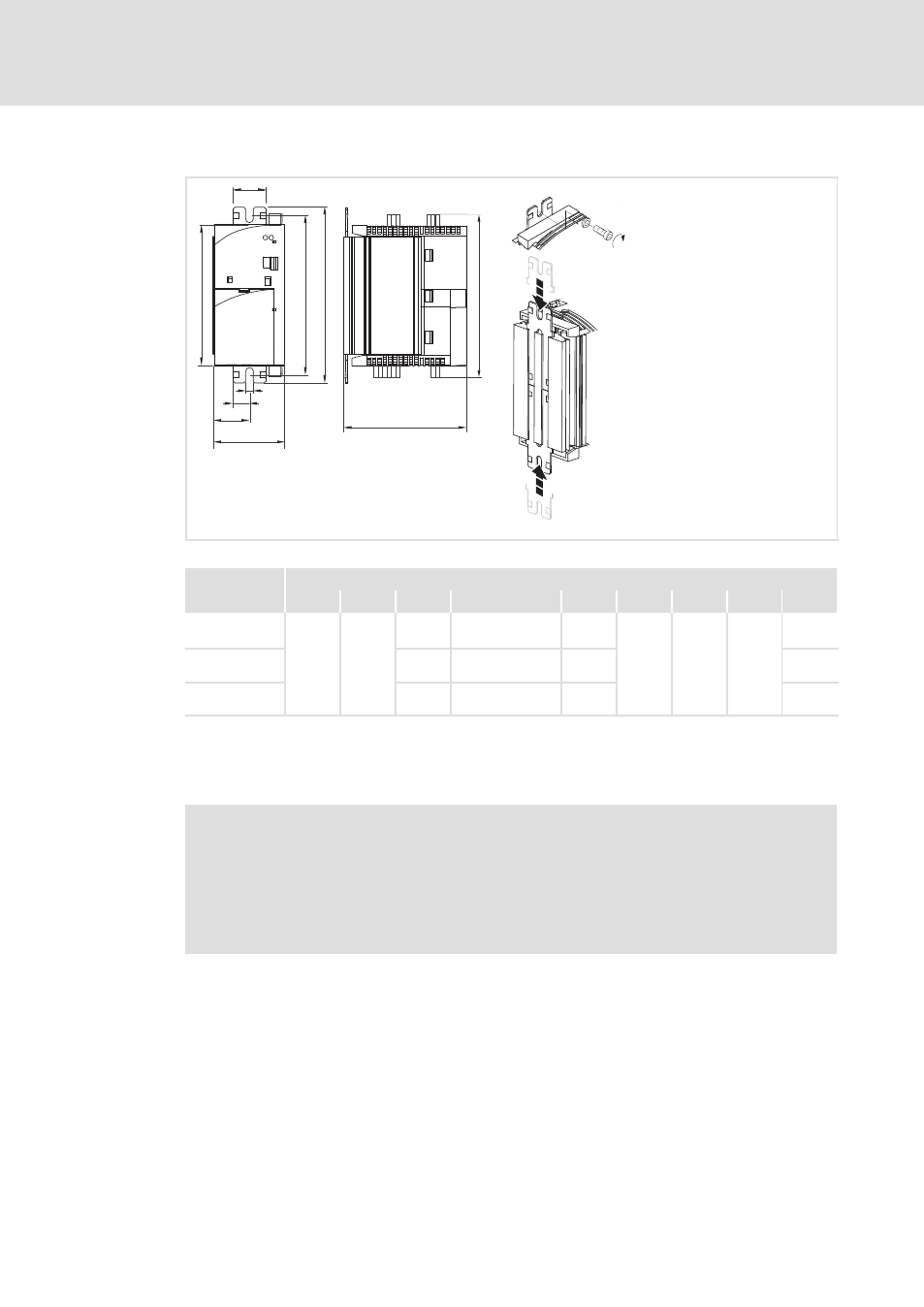
Fig. 5−6
Dimensions for installation in "cold−plate design" 0.25 ... 2.2 kW
Dimensions in [mm]
8200 vector
a
a1
b
b1
b2
c
1
d
e
f
E82CV251K2C
E82CV371K2C
60
30
150
130 ... 140
120
106
6.5
27.5
148
E82CV551KxC
E82CV751KxC
210
190 ... 200
180
208
E82CV152KxC
E82CV222KxC
270
250 ... 260
240
268
1)
If the function module is attached: observe mounting clearance and cable bending radius. The terminals of function
modules in PT design protrude above the housing by 14 mm.
Mounting
)
Note!
ƒ
Apply the heat−conducting paste onto cooler and cooling plate before you
bolt the controller onto the cooler to reduce the heat transfer resistance to
its minimum.
ƒ
The heat−conducting paste supplied in the accessory kit will do for
approx. 1000 cm
2
.
1. Insert fixing rails into the cooling plate from above and below
2. Clean the contact surfaces of cooler and cooling plate with methylated spirit.
3. Use a spatula to apply a thin layer of heat−conducting paste.
4. Bolt the controller tightly together with the cooler using two screws.