3 monitoring the safety function with a plc, Monitoring the safety function with a plc, Safety engineering – Lenze E82xVxxxKxxxxx User Manual
Page 500: Requirements the following conditions must be met, Of the drive (see parameterisation example)
Safety engineering
Functional test
Monitoring the safety function with a PLC
l
500
EDS82EV903 EN 3.0
14.4.3
Monitoring the safety function with a PLC
K
SR
µC
PWM
PWM
CINH
DIGOUT
DC 24 V
Z2
Z1
8200 vector
S1
S2
IN 1
IN 2
IN 3
IN 4
34
X3.1
33
K32
K31
28
Ax
&
8200vec111
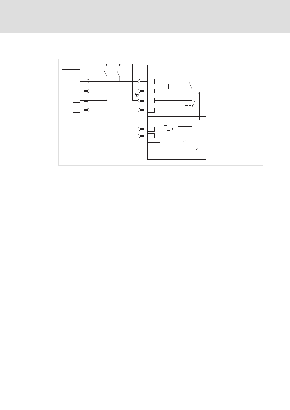
Fig. 14−4
Circuit diagram for monitoring the safety function with a PLC
S1, S2
Separate options for disconnecting the two disconnecting paths
K
SR
Safety relay
X3.1/34
Control of safety relay
X3.1/33
Control of safety relay (GND)
X3.1/K32 Positively driven feedback contact (24 V)
X3.2/K31 Positively driven feedback contact
Z1
Standard I/O or application I/O
Ax
Digital output for motor current evaluation
CINH
Controller inhibit
Z2
Programmable logic controller (PLC)
IN 1 − 4
Digital inputs
Requirements
The following conditions must be met:
ƒ
The PLC must be programmed such that the complete system is set to a safe state
immediately when the function check leads to an impermissible state.
ƒ
The parameter setting of a digital output must be such that you can conclude to the
output current I
motor
of the drive (see parameterisation example).