Adjust lateral offset – Ag Leader GeoSteer Operation Manual User Manual
Page 77
Auto
Calibrate
Operator’s
Manual
63
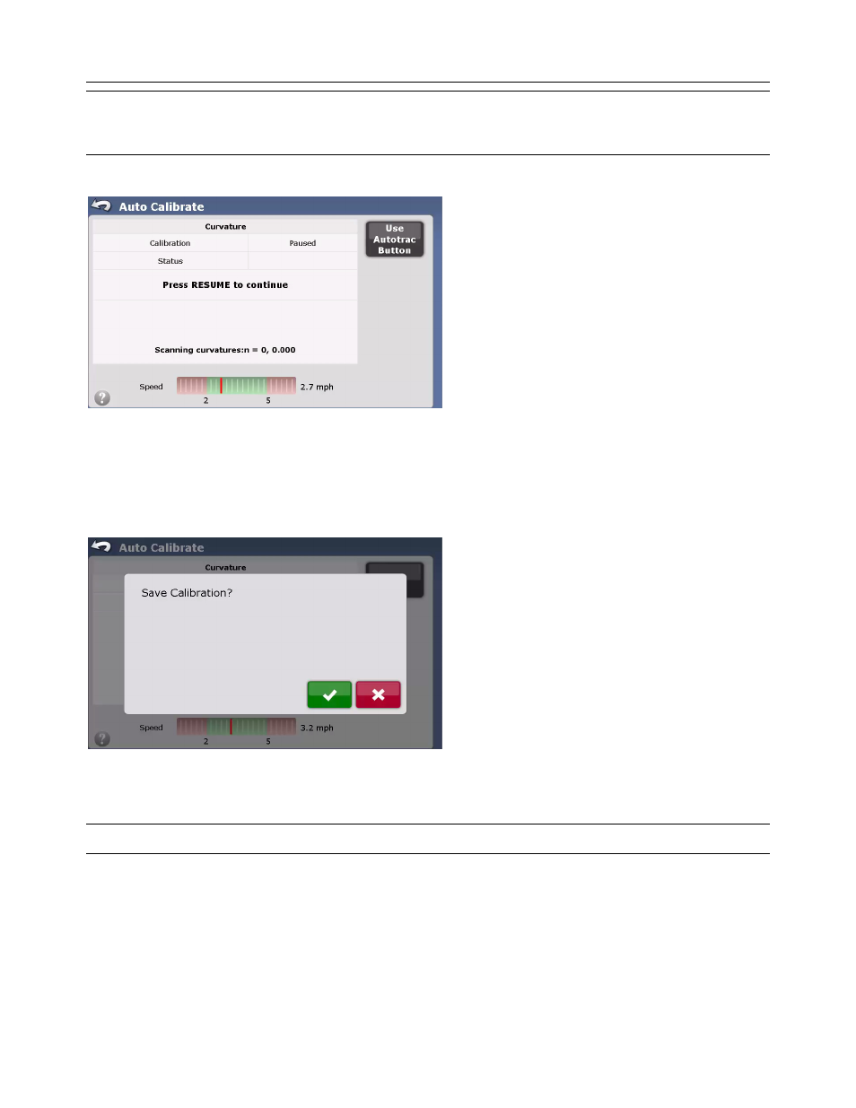
Note: Some CAN Bus / ISO Controlled vehicles require the user to use the vehicle’s factory supplied engage switch to start the
calibration process. If this is require, the calibration screen will notify the user to use that device instead of pressing Resume
on the screen.
Figure 2-65 CAN Bus / ISO Controlled Calibration Start
The vehicle will start by driving in a straight line for a short time, it will then start making increasingly sharp turns to the right
until eventually it reaches the maximum right turn. It will then go back to center and then start making increasingly sharp turns
to the left until it reaches the maximum left turn. Once it gets to the maximum left turn, the calibration will be complete.
Save Calibration
Figure 2-66 Save Calibration
Once the Curvature calibration process has completed, the Save Calibration screen will appear. Press the Green Check button
to accept and save calibration. Press the Red X button to discard all changes.
Note: If the Red X is pressed, the calibration will have to be restarted from the beginning.
Adjust Lateral Offset
After the vehicle has been created and calibrated, perform the following procedure to ensure that the lateral offset is entered
correctly. This procedure will detect and eliminate skips and overlaps in adjacent rows due to an incorrect lateral offset.