Ag Leader GeoSteer Operation Manual User Manual
Page 28
Transferring GeoSteer from Vehicle to Vehicle
14
GeoSteer System
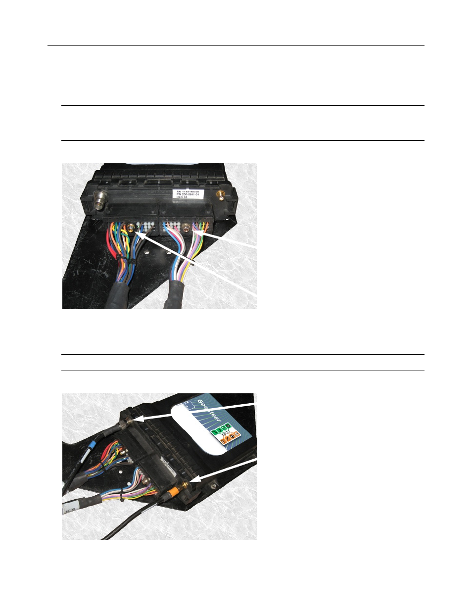
3. Attach the GeoSteer Main Cable Harness connector to the left side connector on the GeoSteer Control Unit. Match the
Yellow dots on the harness to the GeoSteer Control Unit Connector. Use a 1/4 inch nut driver to tighten the connector.
4. Attach the Vehicle Specific Cable Harness (if required) to the right side connector on the GeoSteer Control Unit. Match
the White dots on the harness to the GeoSteer Control Unit Connector. Use a 1/4 inch nut driver to tighten the connectors.
Note: Both connectors are keyed so they will only attach the proper side of the GeoSteer Control Unit and in one
orientation. The connectors should slide easily onto the receptacle. If they do not slide easily, try a different position. Do
not force the connector into the receptacle as this could damage the connectors.
Figure 1-14 Attach GeoSteer Control Unit Harnesses
5. Attach the GPS Coax (Blue) TNC Connector to the GeoSteer Control Unit.
6. If the GeoDock has a Cell Modem connection, attach the Cell Modem (Orange) SMA Connector from the GeoSteer Unit.
Note: Hand tighten the Coax connectors only. Do not use a tool to tighten as this may damage the connectors.
Figure 1-15 Attach Coax Connectors
GeoSteer Main Cable Harness Connector
Vehicle Specific Cable Harness Connector
(if Required)
TNC GPS Coax (Blue) Connector
SMA Cell Modem Coax (Orange) Connector (if
equipped