Can bus / iso controllers – Ag Leader GeoSteer Operation Manual User Manual
Page 76
Auto Calibrate
62
GeoSteer System
Observe the steering wheel as the vehicle drives forward. When the steering wheel moves 1/4 turn to the left press the Moving!
button. Take note of the Left cmd value at the time the Moving! button was pressed in case it needs to be adjusted later. When
this step is complete, the calibration procedure is complete.
Save Calibration
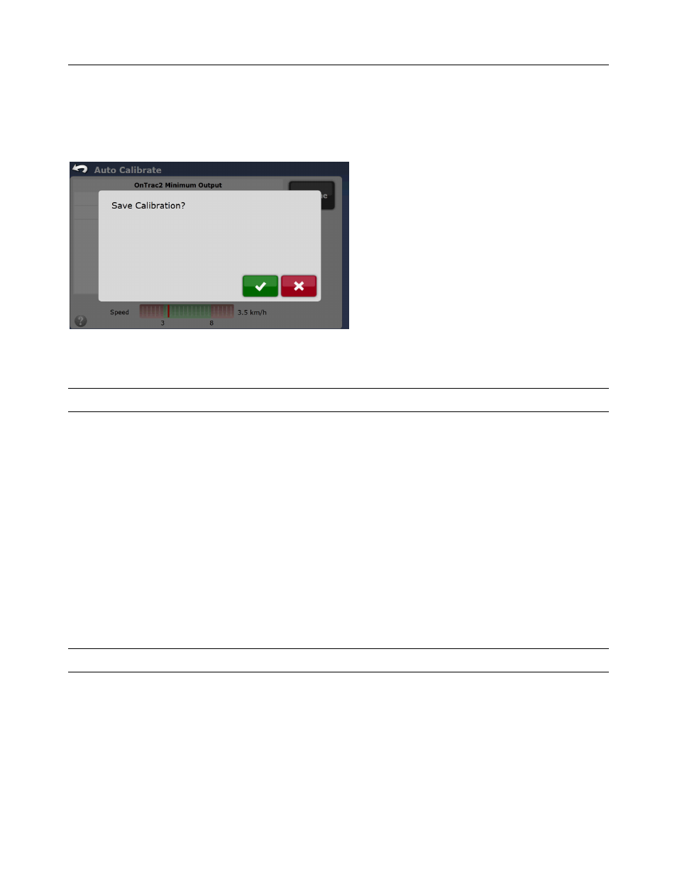
Figure 2-64 Save Calibration
Once the OnTrac2 Minimum Output calibration process has completed, the Save Calibration screen will appear. Press the
Green Check button to accept and save calibration. Press the Red X button to discard all changes.
Note: If the Red X is pressed, the calibration will have to be restarted from the beginning.
CAN Bus / ISO Controllers
This vehicle type uses the CAN Bus or ISO connection on the machine to send steering commands to the vehicle’s steering
controller. The vehicle has an Angle Sensor and Steering Valve built in from the factory. These two components must be
calibrated by the vehicle manufacture so that the vehicle can accurately determine the curvature it will travel at the various
angle sensor readings. The vehicle’s steering valve adjusts the position of the steering axle to get a desired curvature
independently of the GeoSteer system.
For GeoSteer to control these vehicles, the GeoSteer sends a desired curvature command to the vehicle via the CAN Bus. The
vehicle then attempts to adjust the valve to match the desired curvature. There can be some error to what the vehicle thinks the
curvature is as compared to what it actually is. This calibration step compares the estimated curvature the vehicle thinks it is
using to the actual curvature calculated by the GPS system. There is only one step to finish the calibration.
• Curvature – This step compares the estimated curvature from the vehicle to the true curvature as measured by the GPS.
The next step of the calibration process should have started automatically from the Common Calibration Steps.
Note: Verify that the engine RPM is at the working speed while this part of the calibration is taking place.
Curvature
The part of the calibration sends various curvature commands to the vehicle. The vehicle then steers to what it believes is that
curvature value. The GeoSteer system then measures what the actual curvature is using the GPS antennas. To start the
calibration step, start driving the vehicle in a straight line between 2.0 and 5.0 mph (3.2 and 8.0 k/h). Press Resume button to
begin the calibration process.