Geosteer control unit led diagnostics – Ag Leader GeoSteer Operation Manual User Manual
Page 33
GeoSteer Control Unit LED Diagnostics
Operator’s
Manual
19
GeoSteer Control Unit LED Diagnostics
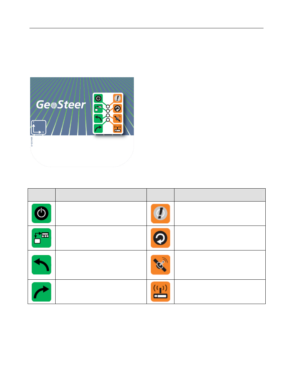
The GeoSteer Control Unit has been designed with four LEDs that can be used to help determine the status of the GeoSteer
system as well as provide some basic troubleshooting information. Figure 1-22 shows the front panel of the GeoSteer Control
Unit. The LEDs will be off, Green, or Amber.
Figure 1-22 Front Panel of GeoSteer Control Unit
Use Table 1-5 for the definitions of the different LEDs and colors.
Table 1-5
GeoSteer Icon Definitions
Green
Icons
Description
Amber
Icons
Description
Solid Green – Indicates good power.
No Color – No power to the GeoSteer Control
Unit.
Flashing Amber – Voltage problem detected in
the GeoSteer Control Unit.
Flashing Green – Indicates communication with
the Display.
No Color – No communication with Display.
Solid or Flashing Amber – System is loading
new firmware to the GeoSteer Control Unit.
Note: Do not cut off power to the GeoSteer
Control Unit while this light is amber.
Green – GeoSteer Control Unit is commanding
actuator to turn left.
No Color – No output being commanded.
Flashing Amber – Displays the number of
satellites being tracked.
Note: The number of quick amber flashes
indicates the number of satellites. Restart
counting after the long pause.
Green – GeoSteer Control Unit is commanding
actuator to turn right.
No Color – No output being commanded.
Flashing Amber – Indicates the GeoSteer
Control Unit is receiving a RTK correction
signal via Radio Modem.