Geosteer height – Ag Leader GeoSteer Operation Manual User Manual
Page 51
Setup
Wizard
Operator’s
Manual
37
Note: The units of measure shown in the AutoSteer Setup pages are configured on the Display side and passed to the GeoSteer
menus. Refer to your Display Operator’s Manual for instructions on how to set the units of measure.
Note: This measurement should be accurate to within 1 inch (2.5 cm).
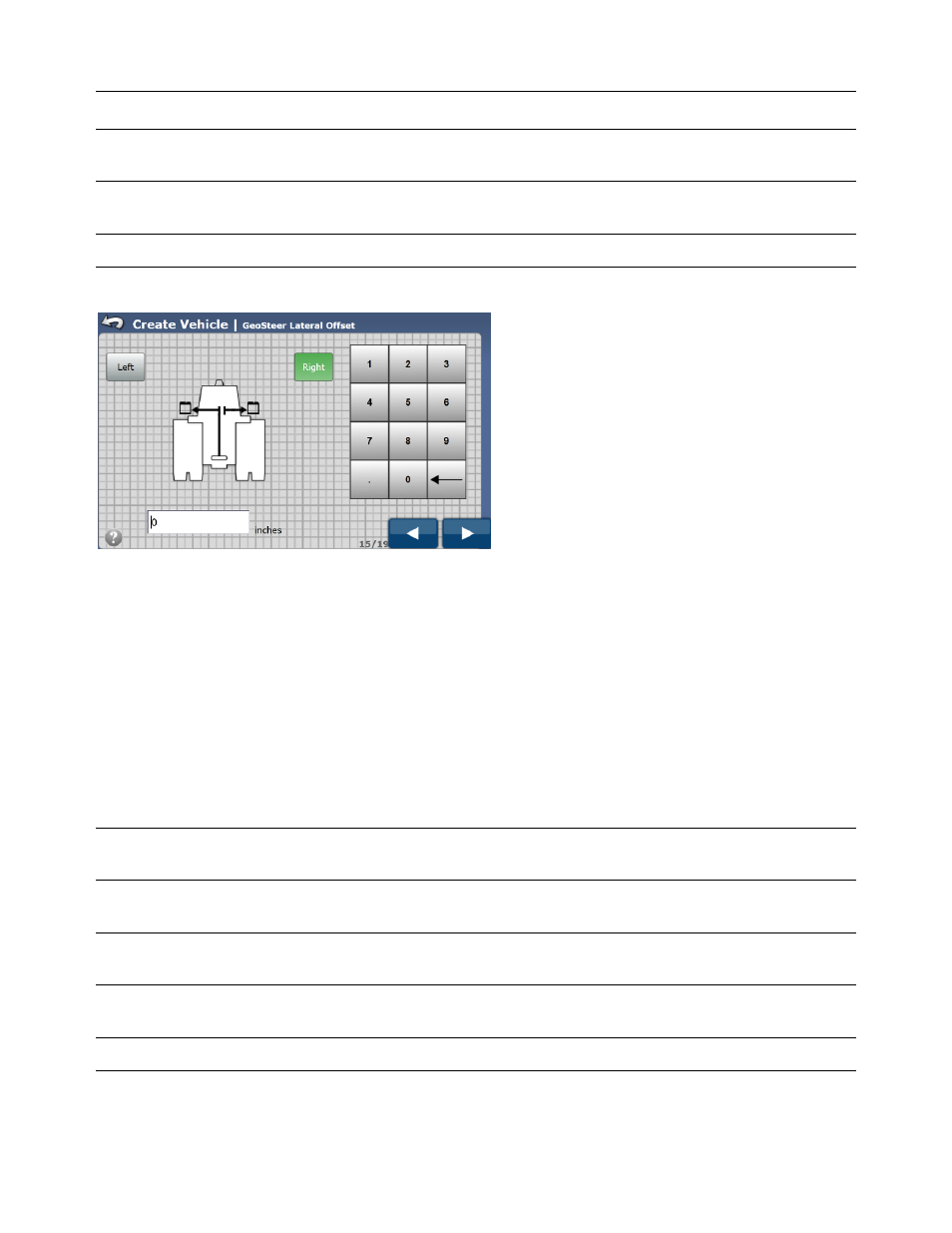
Figure 2-22 GeoSteer Lateral Offset
The GeoSteer Control Unit can be mounted to the left or right side of the centerline. Press the button that indicates which side
of the centerline the GPS antenna is mounted. If the offset is 0.0, it does not matter which one is selected.
• Left – This indicates that the GeoSteer Control Unit is to the left of the centerline.
• Right – This indicates that the GeoSteer Control Unit is to the right of the centerline.
After GeoSteer Lateral Offset has been entered, press the Blue Right Arrow button to continue to the next step.
GeoSteer Height
The GeoSteer Height is the distance from the ground to the center of GeoSteer Control Unit as shown in Figure 2-20. Take a
tape measure and measure the distance from the ground to the GeoSteer Control Unit. Enter that value into the GeoSteer
Height window.
Note: Be sure to verify that the measurement entered is in the same units that the display is expecting. The expected unit of
measurement is shown to the right of the data input box.
Note: The units of measure shown in the AutoSteer Setup pages are configured on the Display side and passed to the GeoSteer
menus. Refer to your Display Operator’s Manual for instructions on how to set the units of measure.
Note: This measurement should be accurate to within 1 inch (2.5 cm).