Ag Leader GeoSteer Operation Manual User Manual
Page 54
Setup Wizard
40
GeoSteer System
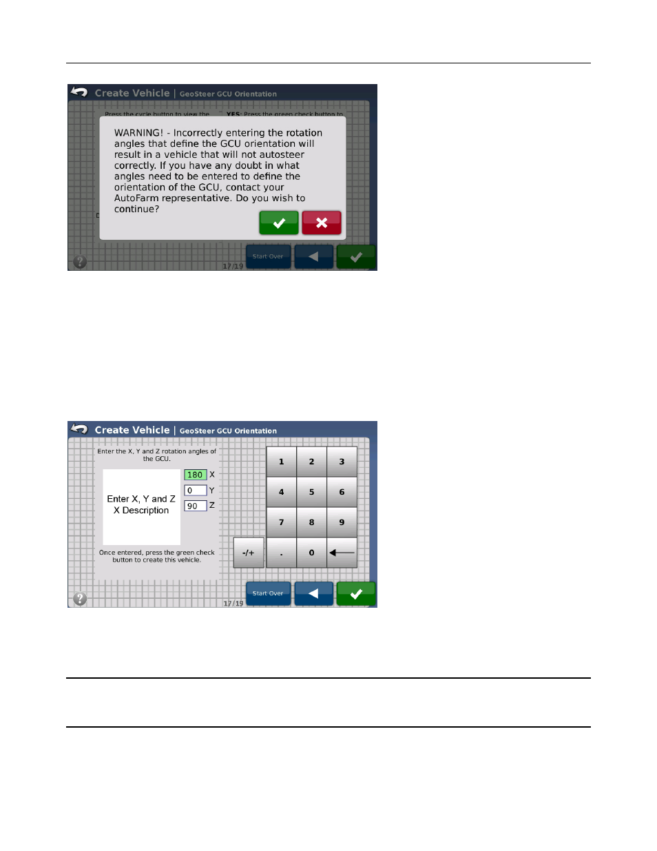
Figure 2-26 GeoSteer Warning
Press the Green Check button only if the angles have been provided by your AutoSteer Dealership. If the angles are not
known, press the Red X button.
Once the Warning screen has been accepted, the GeoSteer expects the user to enter custom angles to tell the system how the
GeoSteer Control Unit is mounted on the vehicle. These angles must be accurate. There are three angles that need to be
entered.
• (X) Pitch – This is the front to back rotation of the GeoSteer Control Unit as compared to the vehicle.
• (Y) Roll – This is the side to side rotation of the GeoSteer Control Unit as compared to the vehicle.
• (Z) Yaw – This is the rotation of the GeoSteer Control Unit compared to the vehicle looking down from the top.
Figure 2-27 GeoSteer Enter Angles
To determine the angles to enter, start with a GeoSteer Control Unit with a rotational settings of (X=0, Y=0, Z=0). This
orientation is with the GeoSteer Control Unit upside down with the connectors pointing to the left side of the vehicle. This is
the Base Orientation Position which all rotations need to be measured from.
Note: Figure 2-28 shows the GeoSteer Control Unit upside down with the connectors pointing to the right side of the vehicle.
This is the Base Orientation that all angle measurements are measured from. The X and Y arrows are not printed on this side of
the GeoSteer Control Unit and are shown only as a reference.