GW Instek PSB-2000 Series User Manual User Manual
Page 20
PSB-2000 Series User Manual
20
8
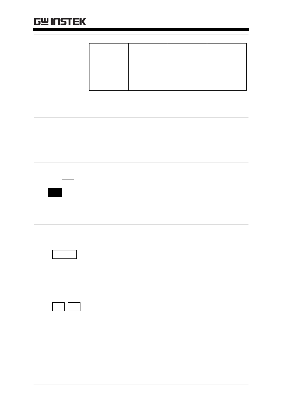
Voltage LED
(7-segment)
Normal
operation
Sequence
operation
Menu
Alarm
Voltage or
power is
displayed.
Cycle No. is
displayed.
Set parameter
is displayed.
OVP, OCP,
HARD or
OHP is
displayed.
The ―W‖ LED on the right of the 7-segment LED
is lit in the power display state.
9
Function
LEDs
These LEDs display the On/Off state of the OFF
TIMER, DELAY or HiΩ functions. The LED is lit
green when the corresponding function is
activated.
10 ESC/DISP
key (ESC /
DISP
)
Changes the channel display, sequence operation
display (i.e., step No. and cycle No.), remaining
time for the off-timer and other displays. When
the menu is displayed, pressing it exits the
function selection mode and returns to the normal
mode.
11 OUTPUT key
(red)
( OUTPUT )
This key turns on or off the output. The LED is lit
when the output is turned on.
12 CH1 and
CH2 keys
(red, green,
orange)
( CH1, CH2 )
These keys turn on or off the channel outputs. The
color of the corresponding LED indicates the
output mode.
Green: CV mode.
Red: CC mode.
Orange: CP mode.
The CH1 and CH2 keys are only available for the
PSB-2400L2 only. The PSB-2400L and PSB-2800L
have single LEDs only.