Audiobus trigger setup detail, Serial data debug solutions 92 – Teledyne LeCroy Serial Data Debug Solutions User Manual
Page 92
Serial Data Debug Solutions
92
919586 RevA
The AudioBus Trigger dialog, with detail on some of the setup conditions, is shown in the following topics.
Note: Refer to Accessing The D and TD Supported Protocol Toolsets (on page 13) for information on finding
the Trigger Condition dialog specific to your desired protocol.
Select condition values by touching fields (using your finger, or use a mouse pointer). A pop-up is shown where
you can choose from Equal, Not Equal, Less than, Less than or Equal to, Greater than, Greater than or Equal to,
In Range, or Out Range condition values.
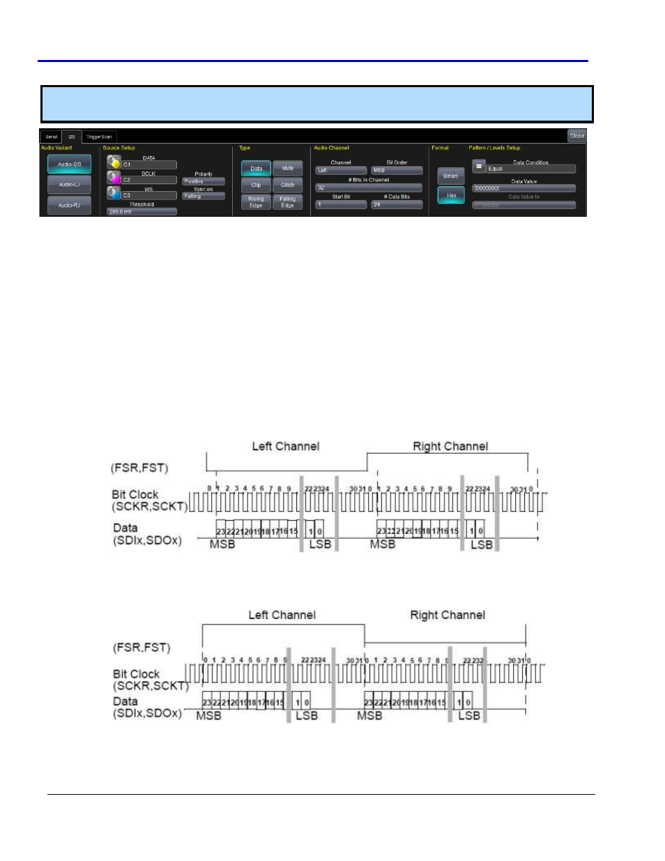
AudioBus Trigger Setup Detail
The detail you provide on this dialog is based on the Audio Variant you select. Certain fields may be enabled
and/or disabled based on your choices.
A
UDIO
B
US
T
RIGGER
D
ETAIL
C
ONSIDERATIONS
Keep the following in mind when setting up your AudioBus trigger details:
Values for I2S data is transmitted with the most significant bit (MSB) first.
MSB is always transmitted 1 clock cycle after framesync transition and the framesync is typically 32-Bits.
Polarity of word select signifies whether data is transmitted from the left or right channel.
Word select transitions indicate the start-of-word position and occur at the sample frequency. Notice
how the following I
2
S illustration shows the MSB occurring one clock cycle after the frame sync transition
I
2
S Variant Timing Format
LJ is similar to I
2
S with the exception that the MSB occurs at the frame sync transition, rather than one
clock cycle after, as follows.
LJ Variant Timing Format