Flexraybus measurement parameter setup, Operator's manual – Teledyne LeCroy Serial Data Debug Solutions User Manual
Page 85
Operator's Manual
919586 RevA
85
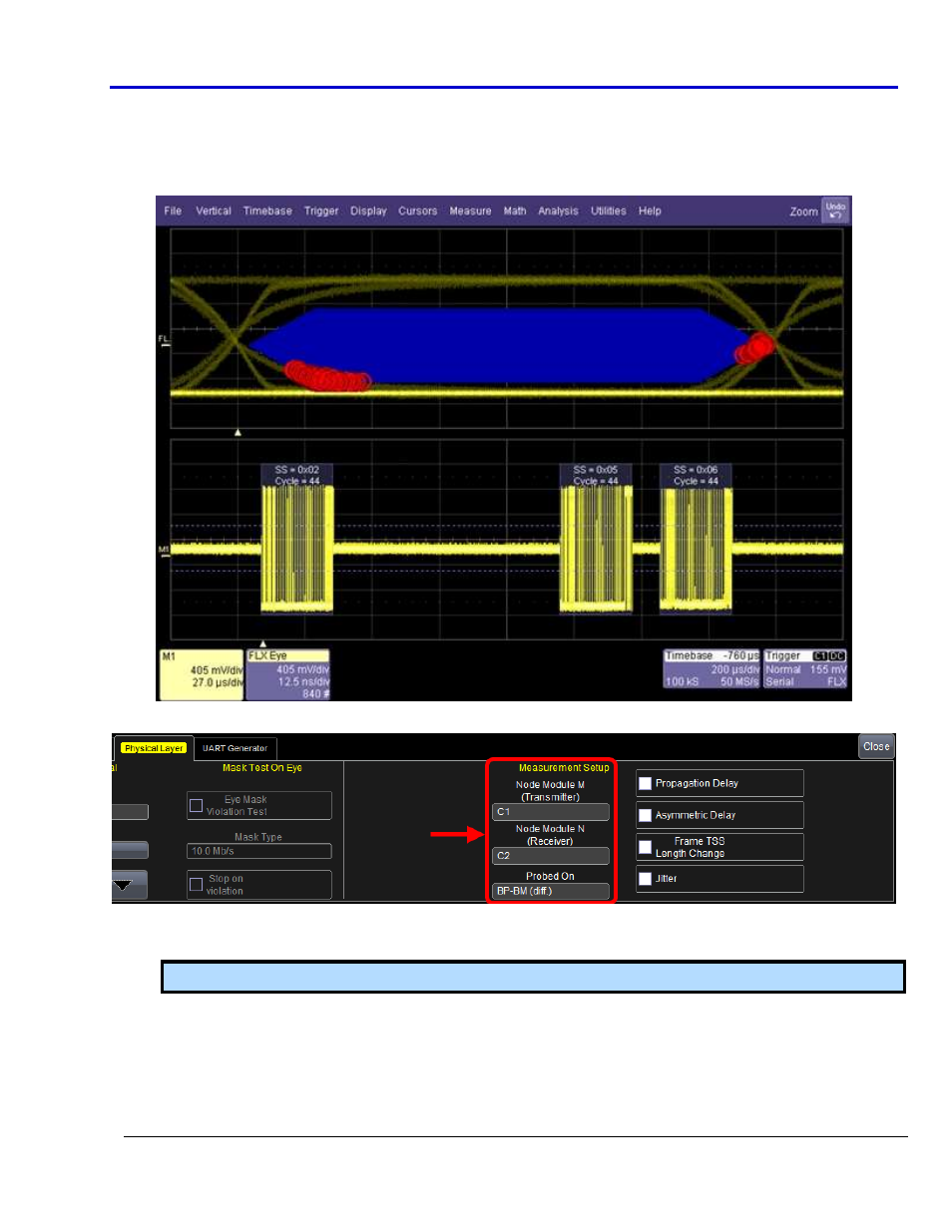
Mask Test Display
The FlexRay TDP option allows you to verify signal integrity of the communication channel and corresponding
protocol data simultaneously as follows. Points where the FlexRay signal intersects the mask are indicated with
red failure marks.
FlexRaybus Measurement Parameter Setup
Source - Select the emitting and receiving nodes (Node Module M and N) on the FlexRay channel where
Propagation Delay, Asymmetric Delay, and Frame TSS Length Change are being measured.
Note: Jitter is measured on a single channel.
Measurements - Select one of the 4 FlexRaybus Physical Layer Measurement Parameters (on page 86).
Measurement values are shown on the oscilloscope display as boxes are marked.
Probing point - Select the type of line on which you are probing as either BP-BM (diff.) if the signal is a
differential signal on the communication channel, or RxD-TxD (dig.) if the signal is the two level digital
signal of the communication controller interface.