C trigger setup detail, Serial data debug solutions 56 – Teledyne LeCroy Serial Data Debug Solutions User Manual
Page 56
Serial Data Debug Solutions
56
919586 RevA
Selection of Trigger Type results in dynamic changes to the I
2
Cbus Trigger dialog. Simple I
2
C triggers, such as
Start, Stop, ReStart, and NoAck, require no additional setup, while frame-based triggers, such as ADDR,
ADDR+DATA, FRAME LENGTH, and EEPROM require addition user-defined setup information.
Select condition values by touching fields (using your finger, or use a mouse pointer). A pop-up is shown where
you can choose from Equal, Not Equal, Less than, Less than or Equal to, Greater than, Greater than or Equal to,
In Range, or Out Range condition values.
I
2
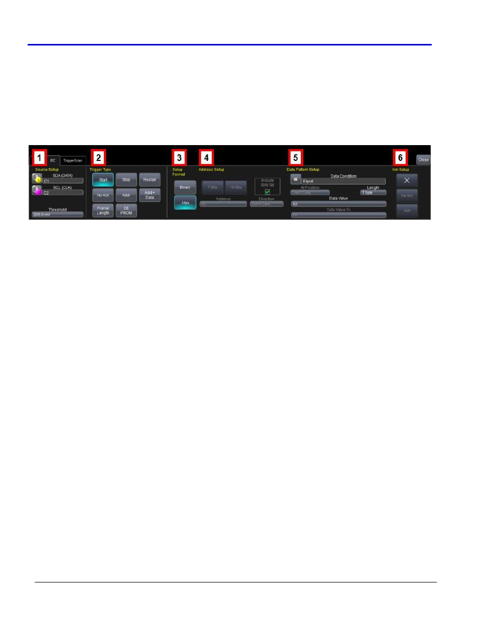
C Trigger Setup Detail
The following topic provides specific control settings for an I
2
Cbus Trigger.
The previously numbered I
2
Cbus trigger sections correspond with the following explanations.
1.
S
OURCES
S
ETUP
DATA and CLOCK - The pop-up dialog is used to select the appropriate channel or EXT inputs for each. Set
these fields up with caution or your trigger may not function correctly.
Threshold (Trigger) - Adjust the vertical level for the trigger. Much like an Edge trigger, a user must
specify the level used in order to process the incoming signals and determine whether the desired serial
data pattern is meeting the set trigger condition. This value is used for both DATA and CLOCK signals.
2.
T
RIGGER
T
YPE
The I
2
C trigger can be configured to trigger on simple conditions; meaning the presence of a START, STOP,
RESTART bit, or the absence of an ACK bit (NO ACK). In addition, more complex trigger conditions can be
created using ADDR, ADDR+DATA, FRAME LENGTH, or EEPROM setups.
If one of the more complex trigger conditions is selected, then reference the following sections for
information on Address and Data Pattern Setup.
3.
S
ETUP
F
ORMAT
Select either Binary or Hexadecimal (Hex) setup mode. The format propagates through the entire I
2
C
trigger setup.
A user can select Binary mode, and set up the address in binary format, then reselect Hex mode and set
up the data in hexadecimal format. Toggling back and forth between the modes does not result in lost
information (binary is used internally as the core format for all triggering and decoding operations),
though use of don’t care bits in a binary setup results in the display of an X (for a full nibble don’t care) or
a $ (for a partial nibble don’t care).
4.
A
DDRESS
S
ETUP
These following setup choices demonstrate ADDR, ADDR+DATA, FRAME LENGTH, or EEPROM Trigger
Selections.
Address Length - I
2
C utilizes either 7 or 10-bit formats for the address, depending on the device. Make the
appropriate selection so as to be able to enter the correct address value.