Operator's manual – Teledyne LeCroy Serial Data Debug Solutions User Manual
Page 49
Operator's Manual
919586 RevA
49
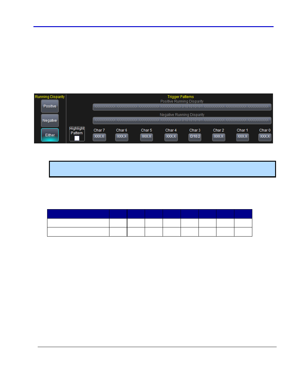
Entering Symbolic 8b/10b Data Patterns
When Symbolic Encoding is selected:
The tab on the High Speed Serial trigger dialog changes to 8B10B
A Running Disparity section is added to the dialog with choices for Positive, Negative, or Either.
A Trigger Pattern section designed for 8b/10b is shown.
Running Disparity selections directly affect the Trigger Pattern fields in a corresponding manner. The Positive
Running Disparity button activates only the Positive Running Disparity field, the Negative activates only the
Negative, and Either activates both. When using Both Running Disparity Trigger Patterns, the system triggers on
the Positive OR the Negative (as indicated on the Trigger On section of the dialog when the values are provided).
Provide your 8b/10b Character values in the Char 7 through Char 0 fields. Provide values by typing
directly into the Data Value field, or double-click the field and use the 8b/10b pop-up keypad.
Note: For more information on specific 8b/10b characters refer to the Encoding Table Reference (on
page 50) topic.
Due to the fact that 8b/10b is a dual-parity protocol, triggering on non-consecutive 8b/10b amounts with
"don't care" values in between is not possible. This is because preceding characters affect subsequent
parity bits.
For Example:
Char 7 Char 6 Char 5 Char 4 Char 3 Char 2 Char 1 Char 0
Valid Trigger Sequence
XXX.X XXX.X K28.5 D10.3 XXX.X XXX.X XXX.X XXX.X
Invalid Trigger Sequence
K28.5 XXX.X XXX.X XXX.X XXX.X XXX.X XXX.X D10.3
The Highlight Pattern check box may be used to shade the portion of the waveform on the grid display
where your data value occurs.
Helpful Trigger Pattern Tools
Binary and Hex Data Patterns have a group of buttons to the right of the High Speed Serial trigger dialog
and can be used to quickly set the pattern to all 0s, all Xs, all 1s, or an inversion of the value provided in
the field.
Saving and Recalling Serial Data Patterns into the Trigger keeps you from having to repeatedly re-enter
them. The serial trigger pattern is also stored in the setup file whenever you save the panel file through
the File → Save Setup dialog. So, the trigger pattern can be recalled simply by recalling the corresponding
panel file. However, the panel setup file saves the entire state of the instrument, which may not always
be desirable. In such cases, use this Save/Recall control to save the Binary, Hex, or Symbolic pattern alone
into CDR (Clock Data Recovery) Pattern.lss files.