Serial data debug solutions 62 – Teledyne LeCroy Serial Data Debug Solutions User Manual
Page 62
Serial Data Debug Solutions
62
919586 RevA
4.
S
ETUP
F
ORMAT
Select either Binary or Hexadecimal (Hex) setup mode. The mode selected affects the format of the
following Data Pattern Equals control.
5.
D
ATA
P
ATTERN
S
ETUP
Data Value - The pattern value is entered in either Binary or Hexadecimal mode depending on the
previous Setup Mode selection . There are two selections for pattern value ‐ Data Value and Data Value
To. The second selection is exposed for entry if the Condition is set to INRANGE or OUT(of)RANGE.
Otherwise, it is grayed out. Up to 12 bytes (96 bits) of data can be entered as a pattern value.
Condition - The DATA condition can be set many different ways. Possible conditions include Equal, Not
Equal, Less than, Less than or Equal to, Greater than, Greater than or Equal to, In Range or Out Range.
Data Bit Position - Specify a specific location in a pattern to trigger on the data value.
Data Bit Length - Specify the number of bits to trigger on, the value may be any number between 1 and
96.
6.
I
NTER
F
RAME
S
ETUP
InterFrame Setup is used to define the position of data in SPI packets. Data is sent in a burst of bits
(usually forming words). Bits are separated by a constant time (and form words with a constant number
of bits). Since packets can include several words and sometimes a signal is encoded over several words,
it's important to establish a bit numbering scheme with a 0 point where counting begins.
Click the appropriate button to select Auto or Manual mode. The Manual mode enables the InterFrame
Time field where you can provide a specific value. Auto mode sets the InterFrame time to four times the
length of a bit.
This is valid with or without chip select; the chip select only marks which bits are considered for signal
inclusion.
Using InterFrame Setup, you can determine how bits are counted in a packet by establishing when to
start counting (which bit is numbered as 0) and when the counter is reset to 0 for the next packet.
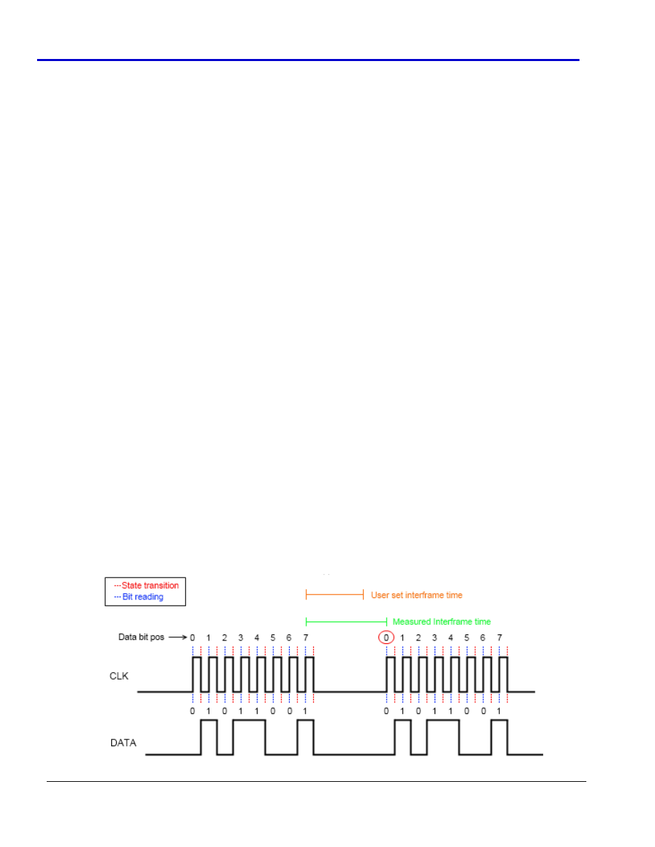
InterFrame Time Explanation
When using Manual mode InterFrame Setup, you can determine when to start counting and when to
reset using the InterFrame Time control. The time between each bit reading transition on the CLK signal is
read. Inside a word, this time is equal to the length of a bit. At the end of a word, the time until the next
transition can be bigger than a bit length. This specific time separation length defines how the bits are
numbered; when the read InterFrame Time is greater than the one you provided, the bit counter is reset
to 0 (as shown in the following image).