C decode setup detail, Serial data debug solutions 54 – Teledyne LeCroy Serial Data Debug Solutions User Manual
Page 54
Serial Data Debug Solutions
54
919586 RevA
Oftentimes, I
2
C utilizes DATA bytes to specify sub-addresses for accessing memory locations in EEPROMs.
Conditional DATA trigger allows triggering on a range of DATA bytes corresponding with reads or writes to
specific sub-address memory blocks in the EEPROM. It can also aid in monitoring DATA outputs from I
2
C- based
sensors, such as analog-to-digital converters, and triggering when DATA is outside a safe operating range. In
both cases, verifying proper operation becomes a simple task. Other powerful and user-friendly features
included in I
2
Cbus TD trigger include:
Ability to define and ADDR or DATA condition in either Binary or Hexadecimal (Hex) formats.
Ability to define an ADDR condition in binary with the DATA condition defined in hexadecimal so as to
trigger on a range of ADDR values using Don’t Care bits.
FRAME LENGTH trigger setups.
EEPROM trigger setups to trigger on up to 96 bits (12 bytes) of DATA at any location within an I
2
C frame or
at a user-defined location in a 2048 byte window.
All permutations of Read, Write, or R/W Don’t Care conditional setup for 7 and 10-bit addresses.
For any I
2
C message trigger, select whether an ACK condition should be ACK, NO ACK, or DON’T CARE. You
can choose to trigger on a NO ACK condition by itself, or as part of a more complex ADDR/DATA trigger.
If you are not familiar with or are just learning about I
2
C, start by using the simplest trigger conditions (Start,
Stop, ReStart, NoAck) to gain confidence, and then set up simple ADDR only conditions. When you are confident
with understanding I
2
C operation, set up an ADDR+DATA condition with a condition of “DATA =”. Then, try
different setups using other DATA conditions (>, <, INRANGE, etc.). Lastly, experiment with the EEPROM trigger
setup, which provides the most flexibility by allowing location of data, with conditions, within specific bytes of a
long sequence of DATA bytes.
Note: Ask your local LeCroy representative for more information about any Serial Data Debug Solution
Protocols or Toolkits using the Contact LeCroy for Support (on page 199) topic.
I
2
C Decode Setup Detail
For general information about using controls shown on the main Serial Decode dialog, refer to Accessing The D
and TD Supported Protocol Toolsets (on page 13).
I
2
C
B
ASIC AND
L
EVELS
R
IGHT
-H
AND
D
IALOGS
Access the Serial Decode dialog by touching Analysis → Serial Decode on the menu bar.
Touch the corresponding Setup... button for your decode. The Decode Setup... along with corresponding right-
hand dialogs are shown.
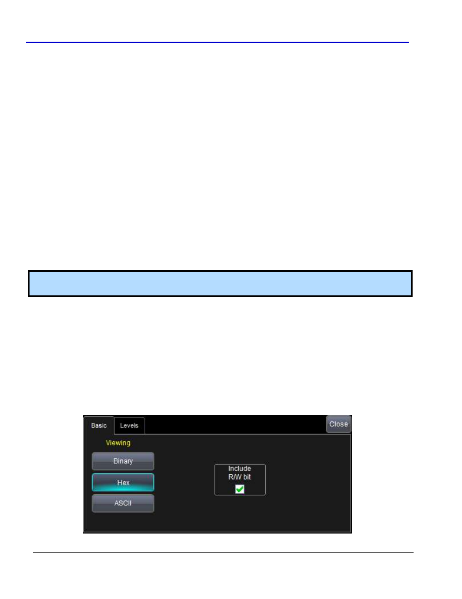
I
2
C Basic Right-Hand Dialog
The Basic right-hand dialog provides detailed controls and setup conditions as follows: