Spibus trigger setup detail, Operator's manual – Teledyne LeCroy Serial Data Debug Solutions User Manual
Page 61
Operator's Manual
919586 RevA
61
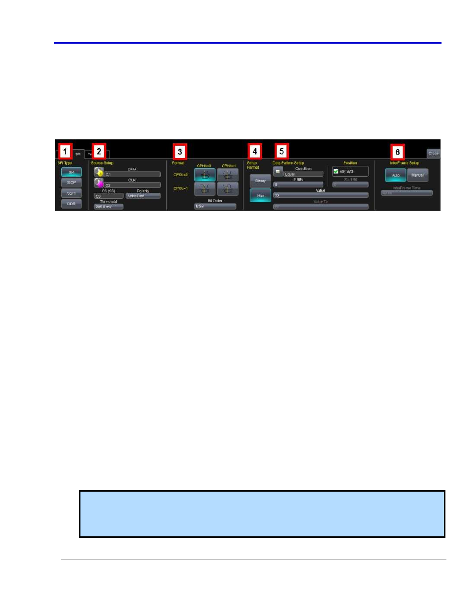
The SPIbus trigger dialog is very flat, meaning there are few dynamic changes to the dialog based on selections
within. The one exception is the SPI Type on the far left. When selecting between SPI, SIOP, and SSPI types, the
dialog to the right changes to reflect a specific setup type.
Select condition values by touching fields (using your finger, or use a mouse pointer). A pop-up is shown where
you can choose from Equal, Not Equal, Less than, Less than or Equal to, Greater than, Greater than or Equal to,
In Range, or Out Range condition values.
SPIbus Trigger Setup Detail
The following topic provides specific control settings for a SPIbus Trigger.
The previously numbered SPIbus trigger sections correspond with the following explanations.
1.
SPI
T
YPE
S
ELECTION
Unlike some other serial data standards (such as I
2
C), SPI is not defined by a single standard; rather, there
are several implementations of SPI based on fixed clock polarities, phase, and whether Chip Select is
present or absent. The basic SPI Type is all-inclusive and the SSPI (Simplified SPI) and SIOP (Synchronous
Serial I/O Port) types are just pre-selected settings in the basic SPI trigger and provided for operator
convenience. SSPI and SIOP do not use a Chip Select line, but are single Master and single Slave
implementations of SPI. The DDR button enables triggering on double data rate SPI signals where data is
transmitted on both the rising and falling edge of the clock.
2.
S
OURCE
S
ETUP
DATA and CLK (CLOCK) - The pop-up dialog is used to select the appropriate channel or EXT inputs for
each. Set these fields up with caution or your trigger may not function correctly.
CS (Chip Select) and Polarity - These fields are enabled (SPI) or disabled (SSPI, SIOP) based on the SPI Type
selected.
If enabled, choose a Channel or EXT, as appropriate, and make a Polarity selection.
Threshold (Trigger) - Adjust the vertical level for the trigger. Much like an Edge trigger, a user must
specify the level used in order to process the incoming signals and determine whether the desired serial
data pattern is meeting the set trigger condition. This value is used for DATA, CLOCK, and Chip Select
signals.
3.
SPI
F
ORMAT
S
ETUP
Clock Polarity and Phase - SPI requires selections made for the clock polarity and phasing of the data to
the clock. SPI microcontrollers and peripherals have settings for CPOL (Clock Polarity) and CPHA (Clock
Phase) that are published in the technical datasheets for those products. Selections are made based on
the SPI Type chosen previously.
Note: When the basic SPI Type is chosen, you can make selections by clicking on the button containing
the graphic that corresponds with your needs as follows:
SPI Mode 0 = CPOL 0 and CPHA 0. SPI Mode 1 = CPOL 0 and CPHA 1. SPI Mode 2 = CPOL 1 and CPHA 0.
SPI Mode 3 = CPOL 1 and CPHA 1.
Bit Order - Select either MSB or LSB format, as appropriate.