Uart-rs232bus trigger setup detail, Serial data debug solutions 66 – Teledyne LeCroy Serial Data Debug Solutions User Manual
Page 66
Serial Data Debug Solutions
66
919586 RevA
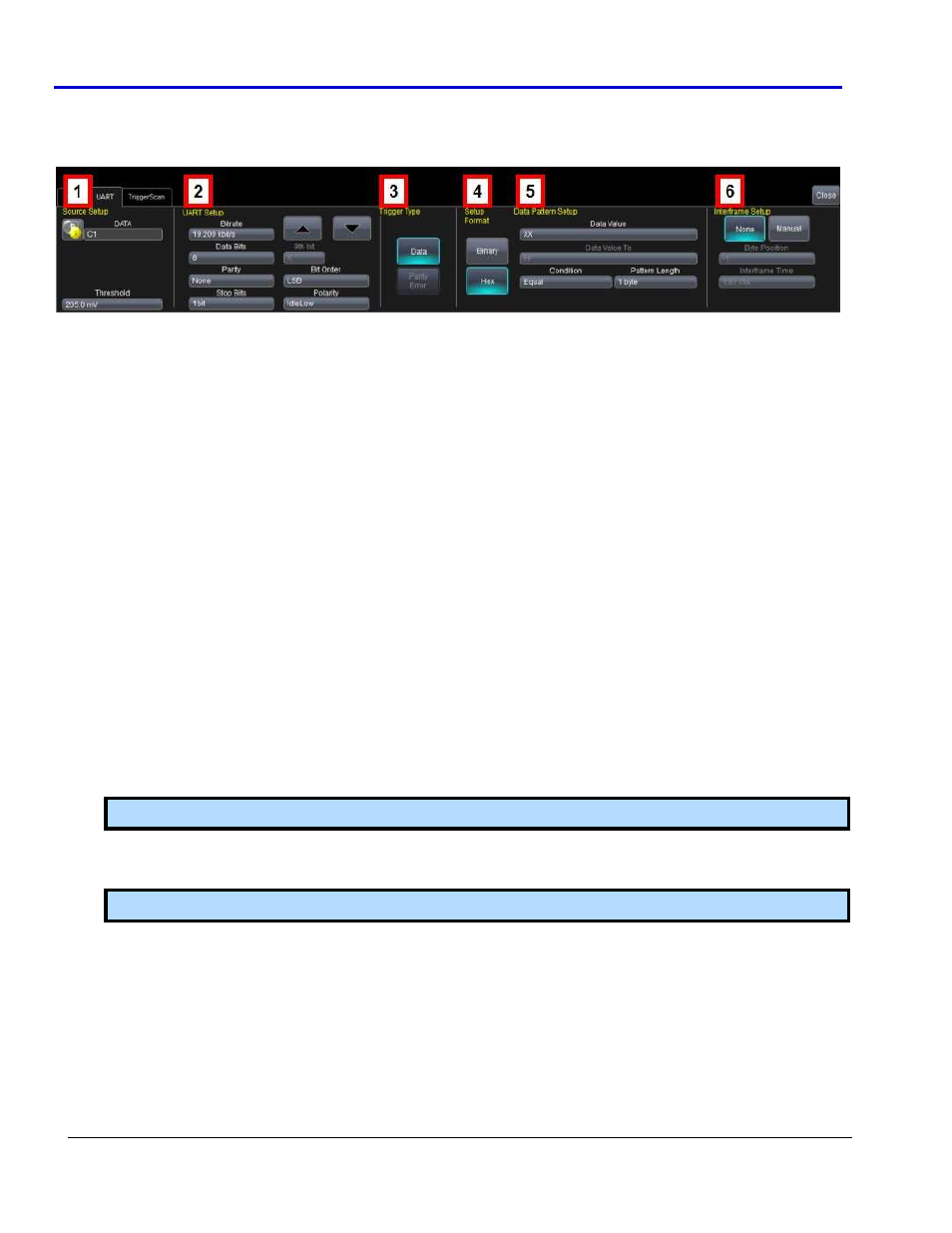
UART-RS232bus Trigger Setup Detail
The following topic provides specific control settings for a UARTbus Trigger (again, since they're almost identical,
but UART contains a bit more detail than RS-232).
The previously numbered UARTbus trigger sections correspond with the following explanations.
1.
S
OURCES
S
ETUP
DATA - The pop-up dialog is used to select the appropriate channel or EXT inputs for each. Set these fields
up with caution or your trigger may not function correctly.
Threshold (Trigger) - Adjust the vertical level for the trigger. Much like an Edge trigger, you must specify
the level used to process the incoming signals and determine whether the desired serial data pattern is
meeting the set trigger condition.
2.
UART
S
ETUP
Bitrate - Use the Bitrate field to adjust the value and match the bus to which you are connected. This
bitrate selection is dynamically linked to the decoding bitrate (they are always the same value). Use the
arrows to move through standard bit rates (300 b/s, 1.2, 2.4, 4.8, 9.6, 19.2, 28.8, 38.4, 57.6, 76.8, 115.2,
230.4, 460.8, 921.6, kb/s, 1.3824 1.8432, 2.7648 Mb/s) and make a selection. Or, touch the number twice
(with a finger, or using a mouse) and open a pop-up keypad and enter the value directly, anywhere
between 30 b/s and 500 Mb/s.
Data Bits - Select the number of data bits per byte (not including the START, STOP, or PARITY bits). Trigger
on UART with a 9
th
DATA bit used as an Alert bit by entering Data Bits = 9, and then define the 9
th
Alert bit
as a 0, 1, or X (don’t care) as needed.
Parity - Choose from Odd, Even, or None in the Parity field. Only when Odd or Even values are made in
this field is the Parity Error Trigger Type enabled.
Stop Bits - Choose 1, 1.5, or 2 Stop Bits in this field.
Bit Order - Choose either Most Significant Bit (MSB) or Least Significant Bit (LSB) bit order in this field.
Note: This field defaults to LSB and cannot be changed on an RS-232 trigger.
Polarity - Choose the Polarity of the UART signal as either IdleLow (Data 1 = High) or IdleHigh (Data 1 =
Low).
Note: This field defaults to IdleLow and cannot be changed on an RS-232 trigger.
3.
T
RIGGER
T
YPE
The Data button is selected by default unless Odd or Even Parity is selected on the Parity field. Then, the
Parity Error Trigger Type button is enabled for use.
4.
S
ETUP
F
ORMAT
Select either Binary or Hexadecimal (Hex) setup mode. The mode selected affects the format of the
following Data Value and Data Value To fields.