Teledyne LeCroy Serial Data Debug Solutions User Manual
Page 33
Operator's Manual
919586 RevA
33
All TD packages provide basic tools to characterize embedded controller performance. The tools can be used on
the decoded channels, memories, zooms, functions, etc. just like they are used on any un-decoded channels,
memories, zooms, functions, etc. You also can use normal Edge or SMART Triggers on an analog channel input to
trigger the oscilloscope when a certain analog signal occurs, and then measure to a particular serial data
message using the decoded info as your guide.
In general, some of these standard tools require a fair amount of manual setup. If the goal is to make many
hundreds or thousands of measurements, you might want to consider using functionality built into the
PROTObus MAG toolset.
Note: The following examples use
messages; however, similar needs exist for other serial data signals,
and the included oscilloscope tools described in the following sections can be applied in the same way.
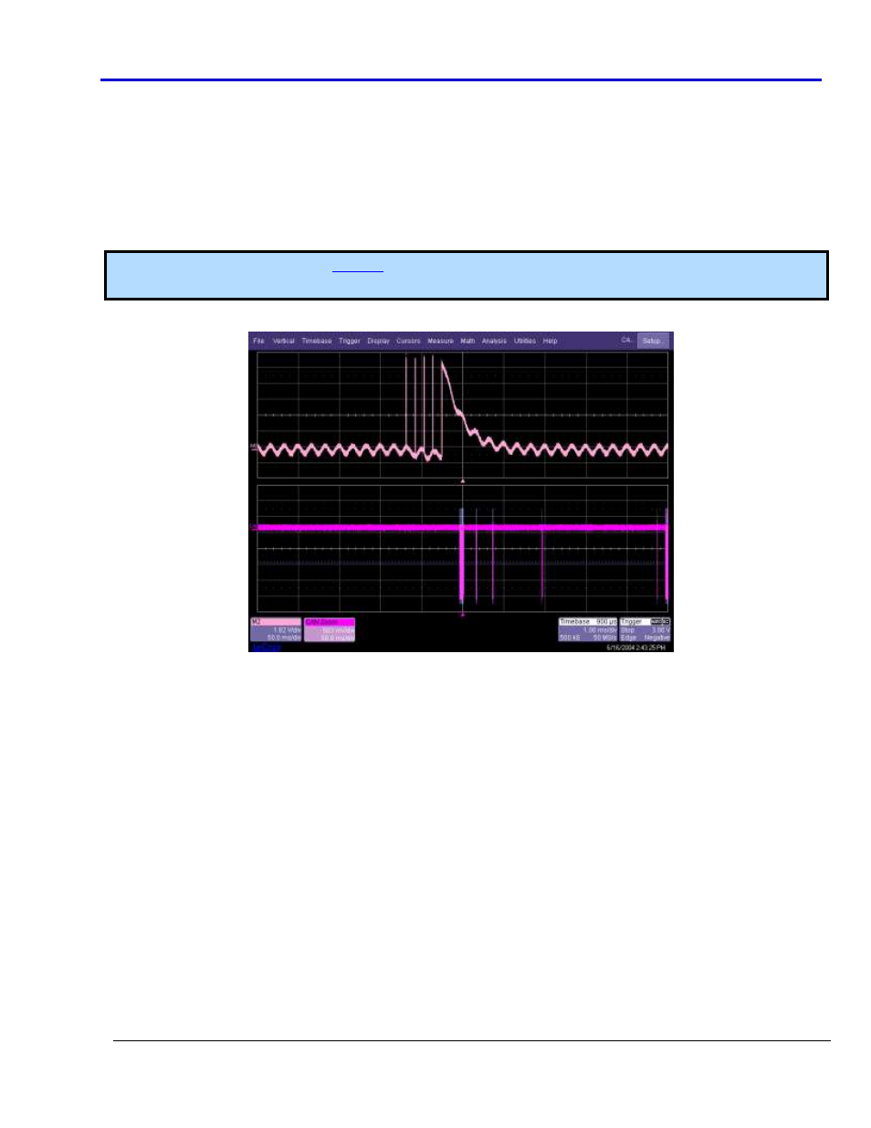
Take the following example of an analog signal creating a burst of CAN messages:
This data was acquired over a 500 ms duration. It is likely you want to understand whether the analog signal
input to your electronic control unit (ECU) is creating the desired CAN message output from the ECU. There are a
few ways this can be done as the following topics explain.