Pciebus decode setup detail, Serial data debug solutions 164 – Teledyne LeCroy Serial Data Debug Solutions User Manual
Page 164
Serial Data Debug Solutions
164
919586 RevA
Correcting Poor Signal Quality or Inverted Signals
It is important to provide a high quality signal when using the Serial Decode package; this is true for PCI Express
decode as well as all the other types. If bits cannot be interpreted correctly the decode, of course, is bad. Notice
how the relatively good quality of the signal shown in the speed change screen-shots towards the end of
PCIEbus Decode Examples (on page 171). The capture was made with a high impedance differential probe at the
add-in card’s driver chip, both for its TX and RX. Do not capture in the middle of the bus (at the PCIE connector)
as reflections may seriously degrade the signal. Also, we used the FFE in the LeCroy Eye Doctor II software
option package to equalize this signal, to further “open the eye.” Signals traversing a significant length of FR4
(printed circuit board material) and coming through a PCIEbus D may show significant degradation at 5 GT/s to
warrant some equalization, depending on the quality of the probe and where it was connected. At 8 GT/s,
equalization is most definitely required, as it is in 8 GT/s PCIe receivers.
An oscilloscope cannot automatically determine if the signal is inverted and compensate like real receivers do.
Therefore, the PCIEbus Decoder tries to parse the signal supplied – it has no choice because, as in the figures
showing speed change, the capture may begin long after link initialization. Therefore it is important to give the
decoder a signal with correct polarity. If the decode table shows lots of UNRECOGNIZED and single bytes of IDL
(basically junk) then the signal probably needs to be inverted.
If the signal is captured with the wrong polarity, it can easily be corrected later. If the capture is two single-
ended waveforms, then just try both subtraction orders; one of them is correct. If the signal is captured using a
differential probe, invert it (if necessary) and refer to the Polarity Correction (on page 195) topic.
Note: Ask your local LeCroy representative for more information about any Serial Data Debug Solution
Protocols or Toolkits using the Contact LeCroy for Support (on page 199) topic.
PCIEbus Decode Setup Detail
For general Serial Decode and Decode Setup... dialog information, refer to the
Serial Decode and Decode Setup
topic. PCIEbus D has additional functionality used to send data to ProtoSync.
S
ENDING
PCIE
BUS
D
D
ATA TO
P
ROTO
S
YNC
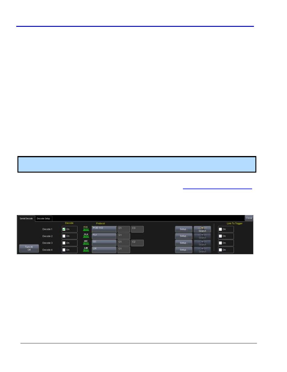
Access the Serial Decode dialog in the oscilloscope software from Analysis → Serial Decode on the menu bar.
At this point, using PCIEbus D decode and exporting to ProtoSync becomes a matter of selecting the appropriate
PCIEbus D decode protocol from PCIE-1X1, PCIE-1X2, and PCIE-4X1 to suit your specific lane needs.
Each of these selections changes the PCIEbus D Decode Setup... dialog in the following ways.