Serial data debug solutions 182 – Teledyne LeCroy Serial Data Debug Solutions User Manual
Page 182
Serial Data Debug Solutions
182
919586 RevA
PLEASE NOTE THE FOLLOWING:
Some additional reserved and vendor-specific FIS values are also available for selection.
Specific FIS values may require additional information. Consult the Serial ATA specification for specific FIS
type details a
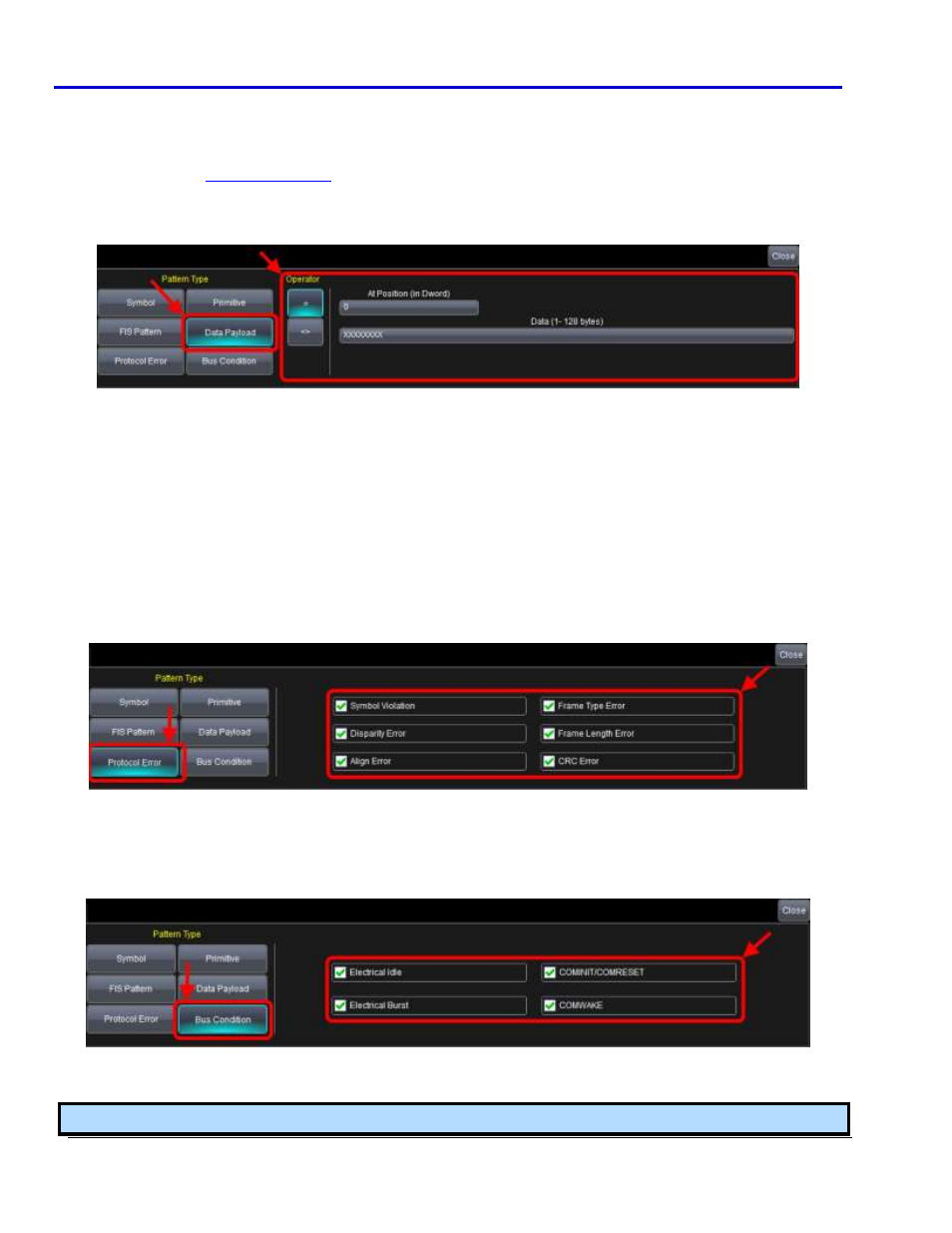
Data Payload Pattern Type Selection Controls
Remaining controls on the dialog vary based on a Data Payload Pattern Type selection in the following manner:
Now, provide values for the controls on the dialog as desired.
Select an Operator from Equal = or Unequal <> values. Selecting Unequal triggers on all data patterns not
matching the one specified.
Use the remaining controls to specify your desired data pattern. The byte order follows a little endian
representation where the least-significant byte is ordered first. Within each byte, the bits must be arranged in a
most-significant bit first order (msb).
Provide a value in the At Position (in Dword) control.
Enter a bit string in the Data (1 - 128 bytes) control.
Protocol Error Pattern Type Selection Controls
Remaining controls on the dialog vary based on a Protocol Error Pattern Type selection in the following manner:
Mark the checkbox adjacent to the protocol error type on which you wish to trigger. Protocol error types
include: Symbol Violation, Disparity Error, Align Error, Frame Type Error, Frame Length Error, and CRC Error.
Bus Condition Pattern Type Selection Controls
Remaining controls on the dialog vary based on a Bus Condition Pattern Type selection in the following manner:
Mark the checkbox adjacent to the bus condition on which you wish to trigger. Bus conditions include: Electrical
Idle On, Electrical Idle Off, Electrical Burst, COMINIT/COMRESET, and COMWAKE.
Note: The Trigger dialog's tab label indicates your Setup Mode selection for convenience.