Creating a canbus trigger condition, Canbus trigger setup detail, Serial data debug solutions 70 – Teledyne LeCroy Serial Data Debug Solutions User Manual
Page 70
Serial Data Debug Solutions
70
919586 RevA
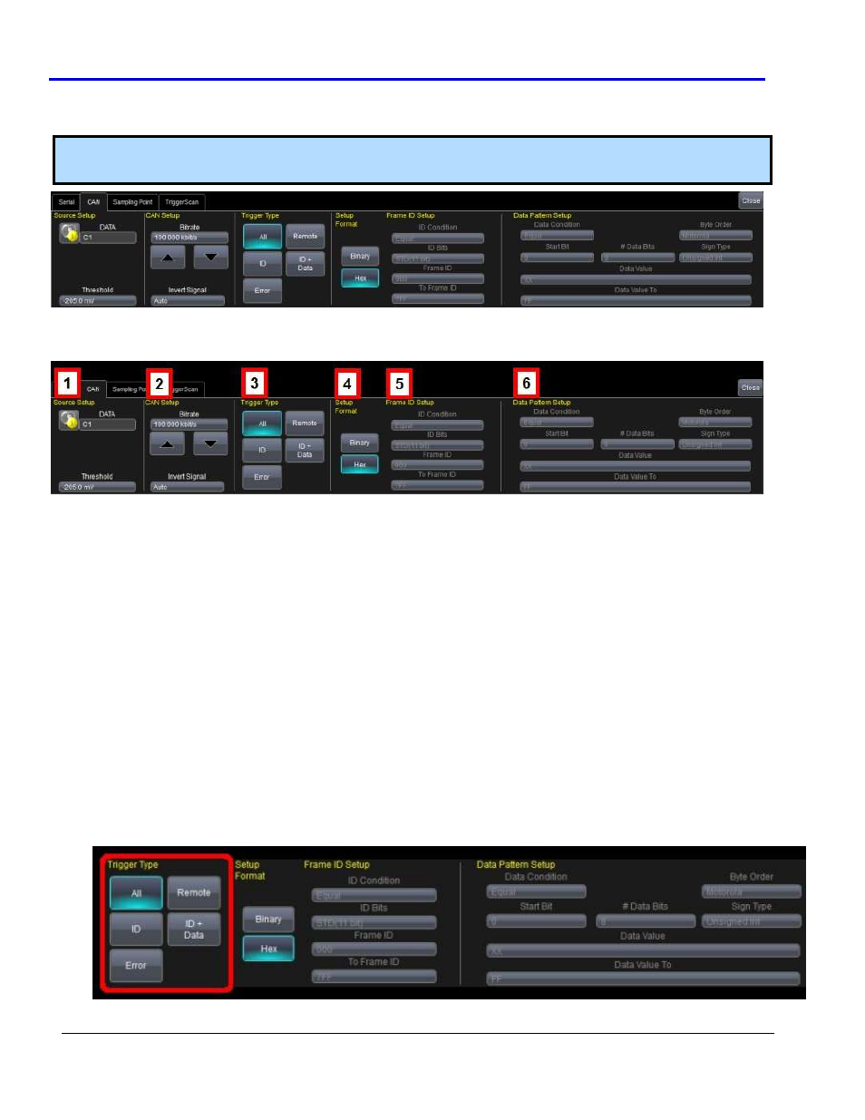
Creating a CANbus Trigger Condition
The CANbus Trigger dialog, with detail on some of the setup conditions, is shown in the following topics.
Note: Refer to Using The D Supported Protocol Toolsets (on page 14) to correctly access the Trigger Condition
dialog specific to your desired protocol.
CANbus Trigger Setup Detail
The following topic provides specific control settings for a CANbus Trigger.
The previously numbered CANbus trigger sections correspond with the following explanations.
1.
S
OURCE
S
ETUP
DATA - The DATA field's pop-up dialog is used to select the appropriate channel or EXT input for each. Set
this field up with caution or your trigger may not function correctly. Use the Threshold field to adjust the
vertical level for the trigger. Much like an Edge trigger, a user must specify the level used in order to
process the incoming signals and determine whether the desired serial data pattern is meeting the set
trigger condition.
2.
CAN
S
ETUP
Bitrate - Use the Bitrate field to adjust the value and match the bus to which you are connected. This
bitrate selection is dynamically linked to the decoding bitrate (they are always the same value). Use the
arrows to move through standard bit rates (10, 25, 33.333, 50, 83.333, 100, 125, 250, 500, and 1000 kb/s)
and make a selection. Or, touch the number twice (with a finger, or using a mouse) and open a pop-up
keypad and enter the value directly.
3.
T
RIGGER
T
YPE
Trigger Type - Depending on your Trigger Type selection, certain Frame ID and Data Pattern Setup fields
are enabled or disabled as follows:
All - Triggers on all signals. No Frame ID and Data Pattern ID Setup fields are enabled.