The catc protocol view, Operator's manual – Teledyne LeCroy Serial Data Debug Solutions User Manual
Page 27
Operator's Manual
919586 RevA
27
Respective protocols in the
Storage, Peripherals, and Interconnects
section of this manual show how
each protocol has their own Exporter right-hand dialog used for sending specific protocol data to
ProtoSync.
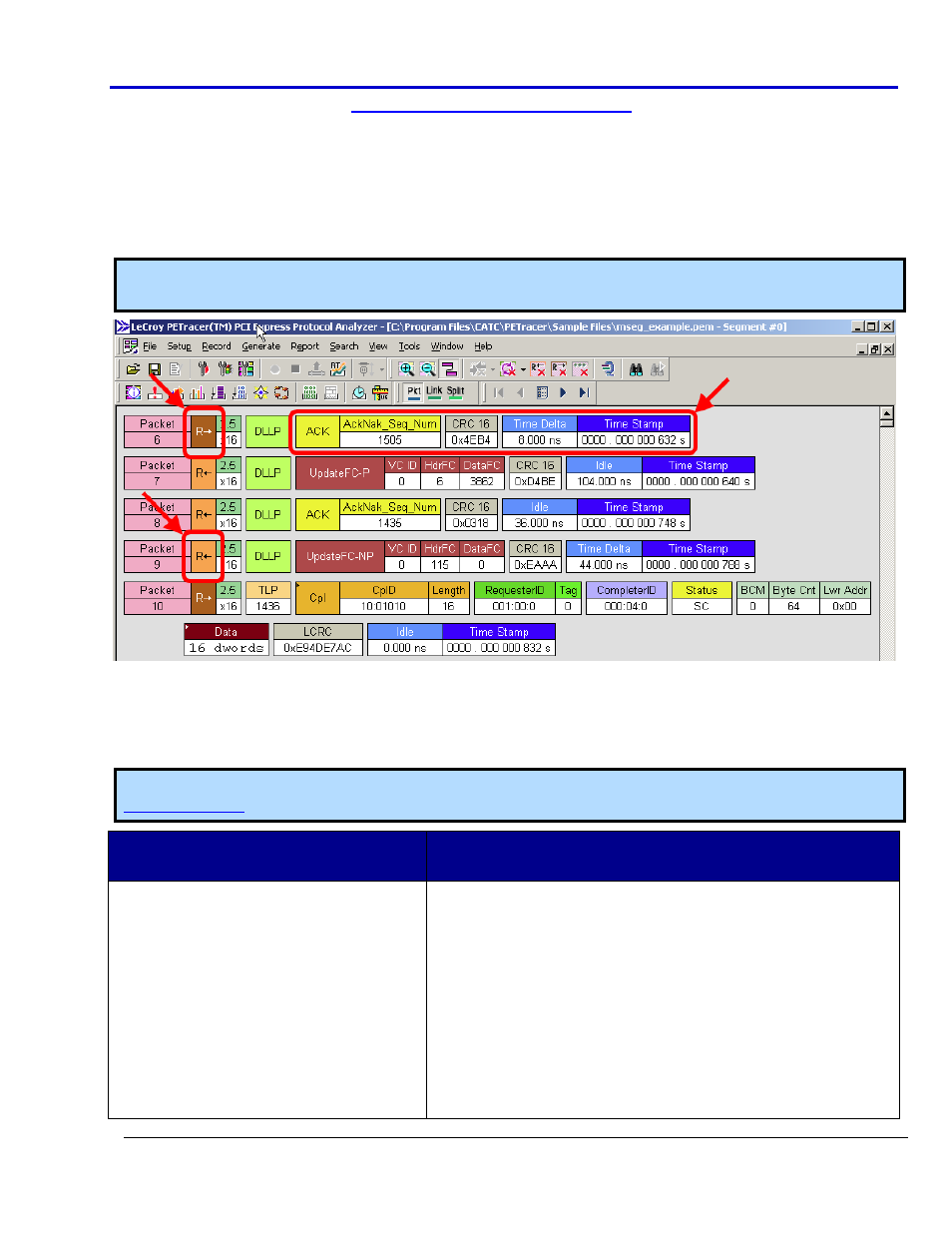
The CATC Protocol View
When ProtoSync is used to generate a protocol packet view of physical layer signals (in the screen-shots, using
the PCIe protocol), data packets are color-coded and shown as rows on the display. Transactions are even shown
as either upstream or downstream (shown here as R→ and R←, respectively for PCIEbus) .
Note: Viewing results look similar when using other Storage, Peripherals, and Interconnect Protocols. See
Storage, Peripherals, and Interconnect Protocols Overview (on page 154) for more information.
D
ECODED
T
ABLE
D
ATA
C
ORRELATES TO
CATC
P
ROTOCOL
D
ATA
While the Decode Annotation Table data is labeled and displayed differently than the CATC Protocol display,
correlation still exists between the two displays. The following table and screen-shots equates some of the
values for the PCIEbus option.
Note: Please refer to LeCroy Protocol Analyzer Software (Voyager, PE Tracer, or Sierra) user manuals at
for information regarding more specific usage when using specific supported protocols.
Label in the PCIEbus D Decode Annotation
Oscilloscope Table Display
Label in PETracer CATC Protocol View
1. Idx
2. Time (µs)
3. Up/Dn
4. Name
5. Repetitions - LeCroy shows one entry
in the table and indicates the number
of repetitions.
6. Details
7. Nominal Rate
1. Packet # - Actual numbers may vary from PCIEbus D decode
annotation table in the oscilloscope to PETracer protocol
packet view since repetitions are handled differently.
2. Time Stamp - Times are likely to differ (see subsequent
note).
3. Upstream (R→) or Downstream ( R← )
4. Packet Name
5. Repetitions - PETracer protocol packet view shows each
repetition as a packet header row in the display.
6. Details - Vary for each packet header type.
7. Packet Header Bit Rate