Operator's manual – Teledyne LeCroy Serial Data Debug Solutions User Manual
Page 15
Operator's Manual
919586 RevA
15
T
HE
D
ECODE
S
ETUP
D
IALOG
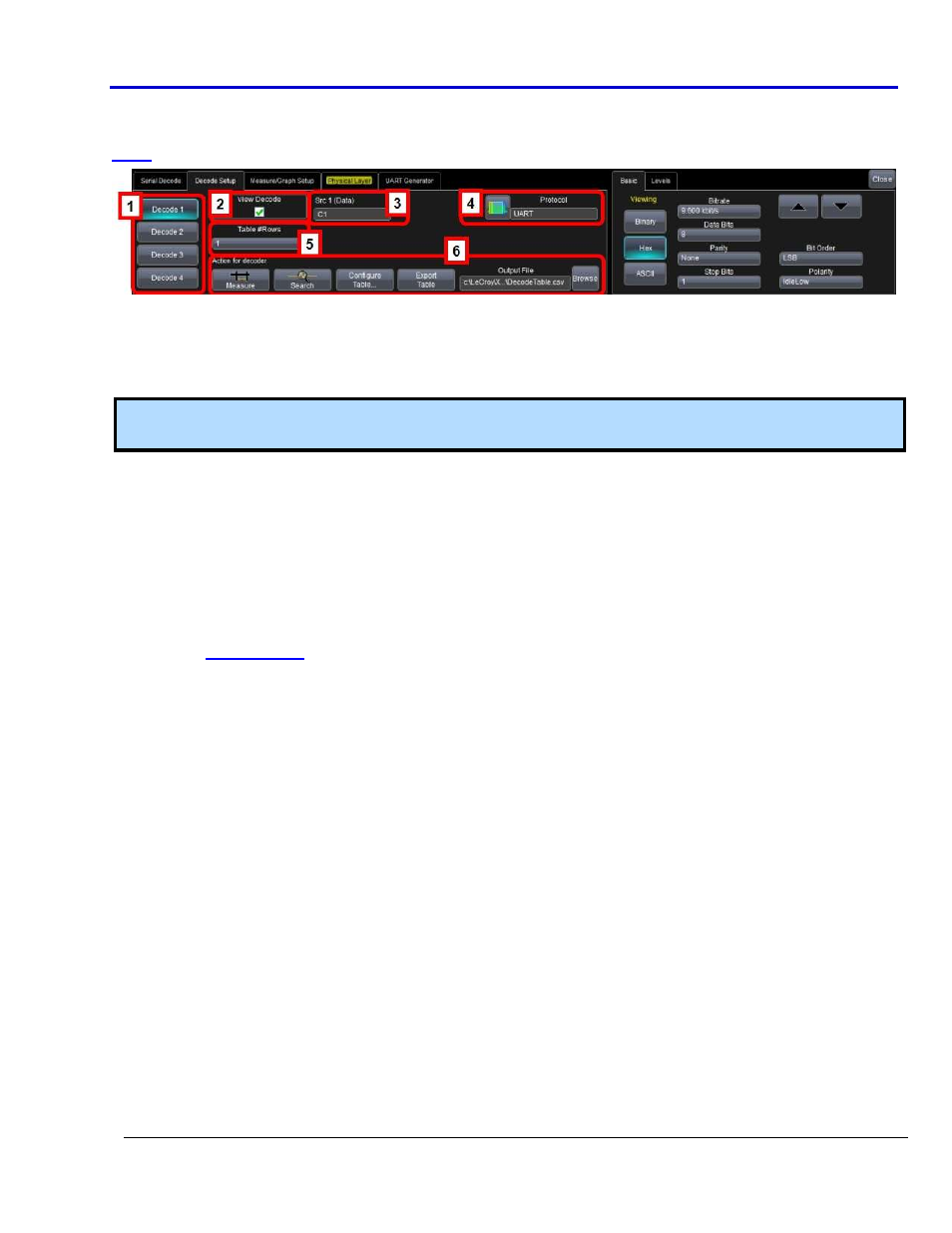
The Decode Setup dialog is where the details of a specific protocol decode is entered. It appears as follows (the
Decode Setup dialog is shown as an example):
This is a single tab with an indicator on the left side describing to which of the four decoders the setup
information pertains.
The left side of this dialog box is described here (the right side is explained in the protocol specific topics).
Numbered callouts correspond with the following explanations.
Note: DigRF 3 and 4G protocols are the only exceptions where a View I & Q button is available in place of
Measure in the Action for decoder section of the main Decode Setup dialog.
1. Decoder # Buttons - Indicates which of the four decoders to which the current information pertains.
2. View Decode Checkbox - Use this checkbox to turn decoding turned ON or OFF for the particular decoder.
Decoding ON provides a highlight of each message frame with color-coded highlighting and decoding of
the various protocol message portions.
PLEASE NOTE THE FOLLOWING:
If the View Decode checkbox is checked, the Table display is also shown. When the View Decode
checkbox is not marked the Table display is not shown.
When the Table is displayed, it appears similar to that shown previous (the example shown is for
The first column heading (top left most cell of the table) bears the name of the corresponding
protocol. The cell's fill color matches the protocol color used on the grid display. Touching this
colorized, first column heading opens the Decode Setup dialog.
Touching the number cell (first cell) for each table row automatically sets up a Zoom for the
corresponding message position.