Accessing the d and td supported protocol toolsets, Operator's manual – Teledyne LeCroy Serial Data Debug Solutions User Manual
Page 13
Operator's Manual
919586 RevA
13
Note: Although the decoding algorithm is based on a clock extraction software algorithm using a vertical level,
the results returned are the same as those from a traditional protocol analyzer using sampling point-based
decode. In addition, the clock extraction technique allows partial decoding of messages in the event of physical
layer noise, in many cases, whereas a protocol analyzer usually cannot. This is a significant advantage for the
LeCroy software algorithm.
If the sampling rate (SR) is insufficient to resolve the signal adequately based on the bit rate (BR) setup or clock
frequency, the protocol decoding is turned OFF to protect the operator from incorrect data. The minimum SR:BR
ratio required is 4:1. It is suggested that you use a slightly higher SR:BR ratio if possible, and use significantly
higher SR:BR ratios if you want to also view perturbations or other anomalies on your serial data analog signal.
S
ERIAL
T
RIGGER
TD options for some supported protocols contain advanced serial data triggering. This serial data triggering is
implemented directly within the hardware of the oscilloscope acquisition system, and contains advanced
algorithms to protocol decode, recognize, and trigger on user-defined serial data patterns. This allows a
recognized serial data pattern to be used to trigger the oscilloscope at a pre-determined time, and other signals
coincident with the desired serial data pattern can be captured simultaneously.
Accessing The D and TD Supported Protocol Toolsets
These respective toolsets are accessed by locating the Serial Decode and Serial Trigger dialogs.
Note: Users approach the Trigger and Decode software options differently. Some use Decode first, and then
Trigger. In fact, LeCroy has a
Link To Trigger
feature used to specifically tie Decoded channels to Triggers.
Currently, the specific protocol content in this Serial Data Debug Solutions manual covers Decode, and then
Trigger tools. Still, the content is clearly titled so no matter what order you access Trigger and Decode
software, the functionality you're looking for is never far.
D
ECODERS
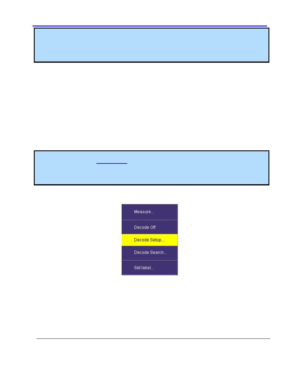
Decoders are all initially accessed by touching Analysis → Serial Decode from the menu bar.
Alternatively, you can also touch a Channel or Memory trace descriptor label showing its corresponding (channel
or memory) dialog, and then touch the Decode button listed shown on the lower part of the dialog. If a decode
table is already displayed, you can shortcut to the decode setup by touching the color-coded protocol name in
the upper-left corner of the decode table itself. See Protocol Results Table (on page 19) for more information.