Technical data, Dp alarm mode, Profibus pdi/pdos – Burkert Type 8717 User Manual
Page 31
31
PROFIBUS DP Start-up
4.2.
Technical Data
GSd file BUV10627.GSd
Symbols BUV10627.BMP address 0 – 126
Standard: 126
4.3.
Dp alarm mode
dP alarm mode is not supported.
Siemens-specific:
Use value "
DPV0" in the hardware configurator. There is no change in the communication protocol.
The value changes only the "alarm mode support".
Additional information is available in the Simatic S7 help.
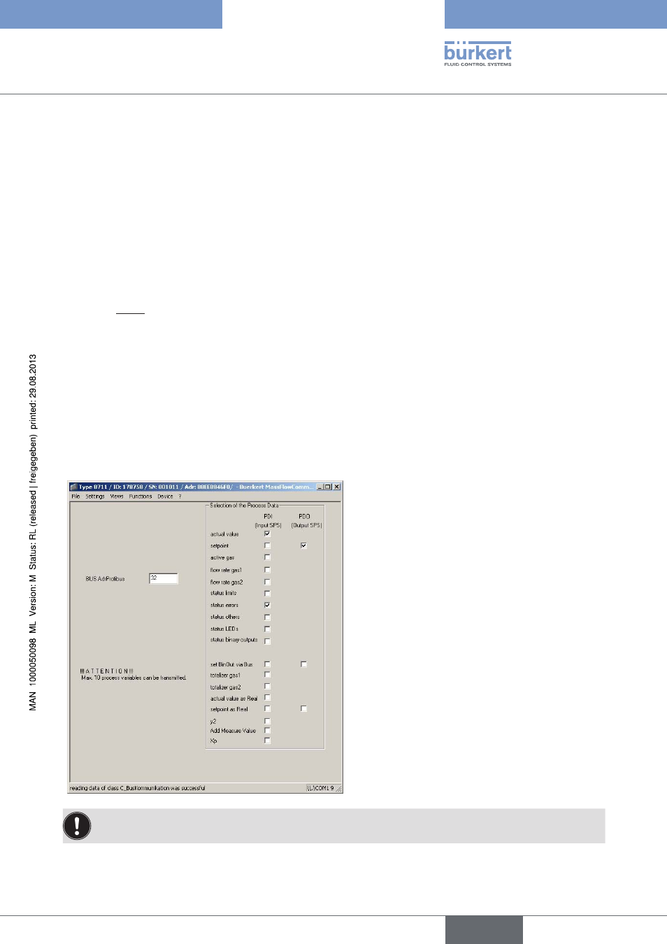
4.4.
prOFiBuS pDi/pDOs
You can make all settings required for bus communication in this input window. The important items are the
BUS address of the device (BUS AdrProfibus) and the process data to be send (input SPS or PdIs) and to be
received (output SPS or PdOs). They can be activated and deactivated with the option fields.
→
Apply the changed settings in the menu bar under "
Functions" / "Write Data to Device".
No more than 10 process data items may be selected. This includes both process input data items and
process output data items.
english
MFC Family