Burkert Type 8693 User Manual
Page 71
71
Installation
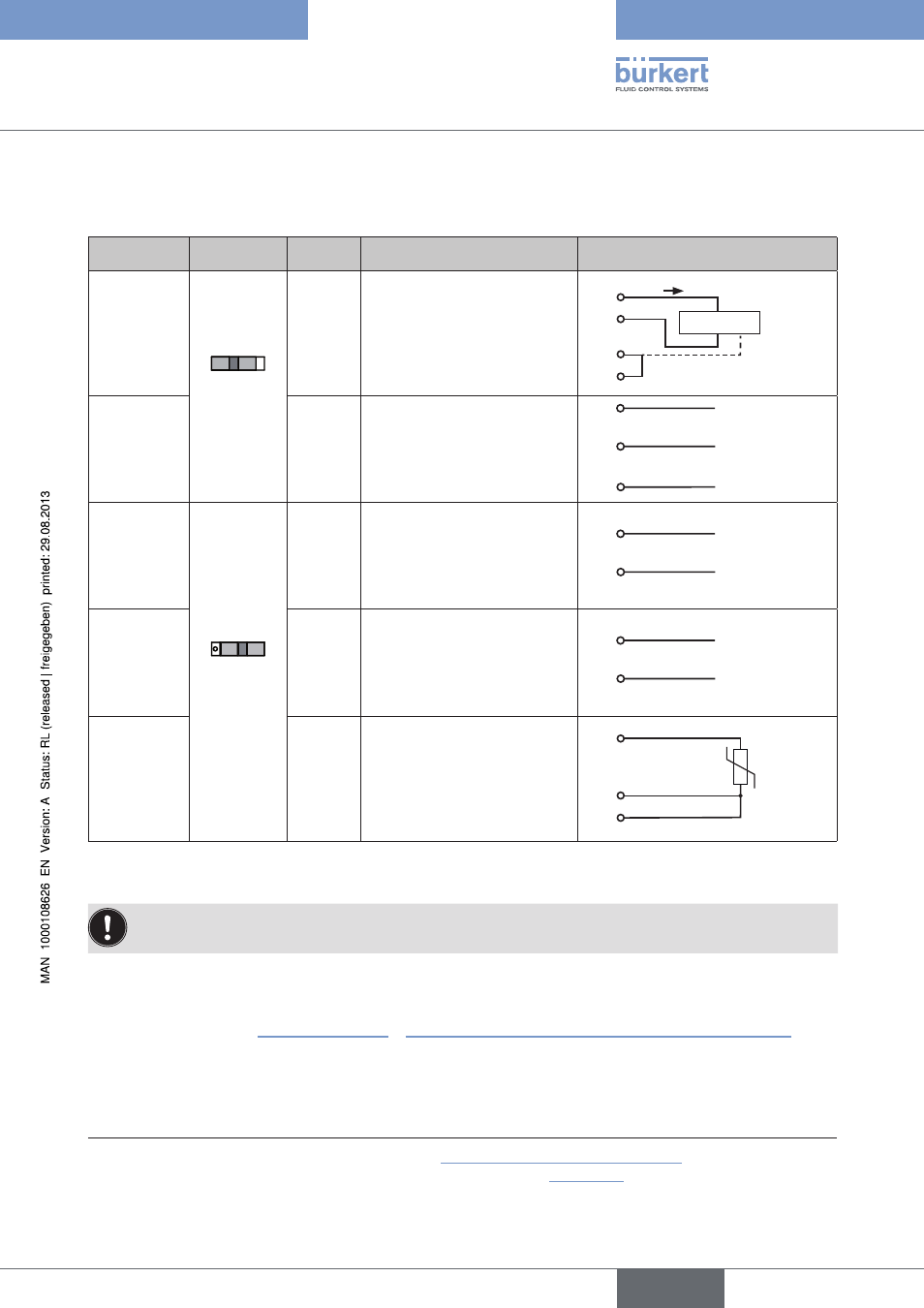
18.4.1. Terminal assignment when selecting the process actual
value input
Input.type
14)
Switch
15)
Terminal Configuration
External.circuit
4 – 20 mA
- internally
supplied
Switch
on left
1
2
3
4
+ 24 V transmitter input
Transmitter output
Bridge after GND (GND from
3-wire transmitter)
GND
GND
1
2
3
4
Transmitter
I
Frequency
- internally
supplied
1
2
3
4
+ 24 V sensor supply
Clock input +
Not assigned
Clock input - (GND)
1
2
4
+ 24 V
Clock +
Clock - (GND)
4 – 20 mA
- externally
supplied
Switch on
right
1
2
3
4
Not assigned
Process actual +
Process actual -
Not assigned
2
3
GND
+ (4 – 20 mA)
Frequency
- externally
supplied
1
2
3
4
Not assigned
Clock input +
Not assigned
Clock input -
2
4
Clock -
Clock +
Pt 100
(see infor-
mation
below)
1
2
3
4
Not assigned
Process actual 1 (current feed)
Process actual 2
(compensation)
Process actual 3 (GND)
Pt 100
2
3
4
Table 23:
Process actual value input
For reasons of wire compensation connect the Pt 100 sensor via 3 wires.
Always bridge Terminal 3 and Terminal 4 on the sensor.
When the power supply voltage is applied, the positioner is operating.
→
Now implement the required basic settings and activate automatic adjustment of the positioner as described
in the chapter entitled “19. Initial start-up” or “Starting and setting up the process controller Type 8693”.
14)
Can be adjusted by software (see chapter entitled “19. 3 Specifying the basic settings”)
15)
The switch is situated on the terminal board of the positioner (see “Figure 33”)
english
Type 8692, 8693