Process actual value (circular plug m 8, 4 pole) – Burkert Type 8693 User Manual
Page 63
63
Installation
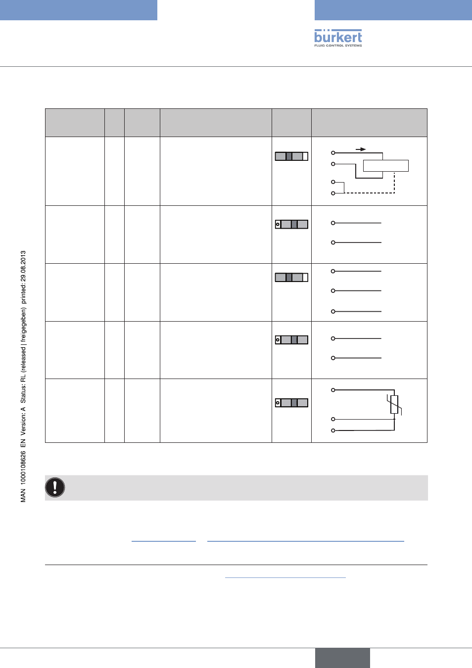
17.5.1. process actual value (circular plug m 8, 4 pole)
Input.type
11)
Pin
Wire.
color
12)
Configuration
Switch
External.circuit
4 – 20 mA
- internally
supplied
1
2
3
4
brown
white
blue
black
+ 24 V transmitter supply
Output from transmitter
GND
Bridge after GND (GND from
3-wire transmitter)
Switch
on
left
GND
1
2
3
4
Transmitter
I
4 – 20 mA
- externally
supplied
1
2
3
4
brown
white
blue
black
Not assigned
Process actual +
Not assigned
Process actual -
Switch
on right
2
4
GND
4 – 20 mA
Frequency
- internally
supplied
1
2
3
4
brown
white
blue
black
+ 24 V sensor supply
Clock input +
Clock input - (GND)
Not assigned
Switch
on
left
1
2
3
+ 24 V
Clock +
Clock -
Frequency
- externally
supplied
1
2
3
4
brown
white
blue
black
Not assigned
Clock input +
Clock input -
Not assigned
Switch
on right
2
3
Clock -
Clock +
Pt 100
(see infor-
mation below)
1
2
3
4
brown
white
blue
black
Not assigned
Process actual 1 (current feed)
Process actual 2 (GND)
Process actual 3
(compensation)
Switch
on right
Pt 100
2
3
4
Table 19:
Process actual value
For reasons of wire compensation connect the Pt 100 sensor via 3 wires. Always bridge Pin 3 and Pin 4
on the sensor.
When the supply voltage is applied, the positioner is operating.
→
Now implement the required basic settings and activate automatic adjustment of the positioner as described
in the chapter entitled “19. Initial start-up” or “Starting and setting up the process controller Type 8693”.
11)
Can be adjusted by software (see chapter entitled “19.3 Specifying the basic settings”)
12)
The indicated colors refer to the connecting cable available as an accessory (918718)
english
Type 8692, 8693