Table4.4 pci memory [0] address map, Table4.5 pci memory [1] address map, Pci memory [0] address map – Avago Technologies LSI53C1020 User Manual
Page 111: Pci memory [1] address map
I/O Space and Memory Space Register Descriptions
4-33
Version 2.4
Copyright © 2001–2004 by LSI Logic Corporation. All rights reserved.
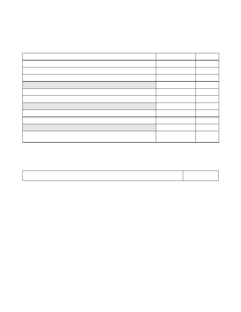
defines the PCI Memory Space [0] address map.
defines the PCI Memory Space [1] address map.
A bit level description of the PCI Memory and PCI I/O Spaces follows.
Table 4.4
PCI Memory [0] Address Map
31
0
Offset
Page
0x0000
0x0004
0x0008
0x000C
Reserved
0x0010–0x002F
–
0x0030
0x0034
Reserved
0x0038–0x003F
–
0x0040
0x0044
Reserved
0x0048–0x007F
–
Shared Memory
0x0080 –
0x(Sizeof(Mem0)-1)
–
Table 4.5
PCI Memory [1] Address Map
31
0
Diagnostic Memory
0x0000 –
0x(Sizeof(Mem1)
−
1)
This manual is related to the following products: