Enabling internet access, Non-transparent mode internet access – Amer Networks E5Web GUI User Manual
Page 345
clients located behind a security gateway operating in transparent mode. In this case, cOS Core
must be correctly configured as a DHCP relayer to correctly forward DHCP traffic between users
and the DHCP server.
It may also be the case that the exact IP address of the DHCP server is unknown but what is
known is the Ethernet interface to which the DHCP server is connected.
To enable DHCP requests to be relayed through the security gateway, the following steps are
needed:
•
Define a static route which routes the IPv4 address 255.255.255.255 to the interface
connected to the DHCP server.
•
Define a static ARP table entry which maps the MAC address FF-FF-FF-FF-FF-FF to the IPv4
address 255.255.255.255 on the interface connected to the DHCP server.
•
Configure a DHCP Relay object with the following property settings:
i.
Set the Source Interface to be the interface connected to the clients.
ii.
Set the DHCP server to relay to to be 255.255.255.255.
iii.
Enable the option: The relayer uses the IP of the interface which it uses to send
requests to the server.
Further explanation of setting up DHCP relay with cOS Core can be found in Section 5.3, “IPv4
DHCP Relay”.
4.8.2. Enabling Internet Access
A common misunderstanding when setting up Transparent Mode is how to correctly set up
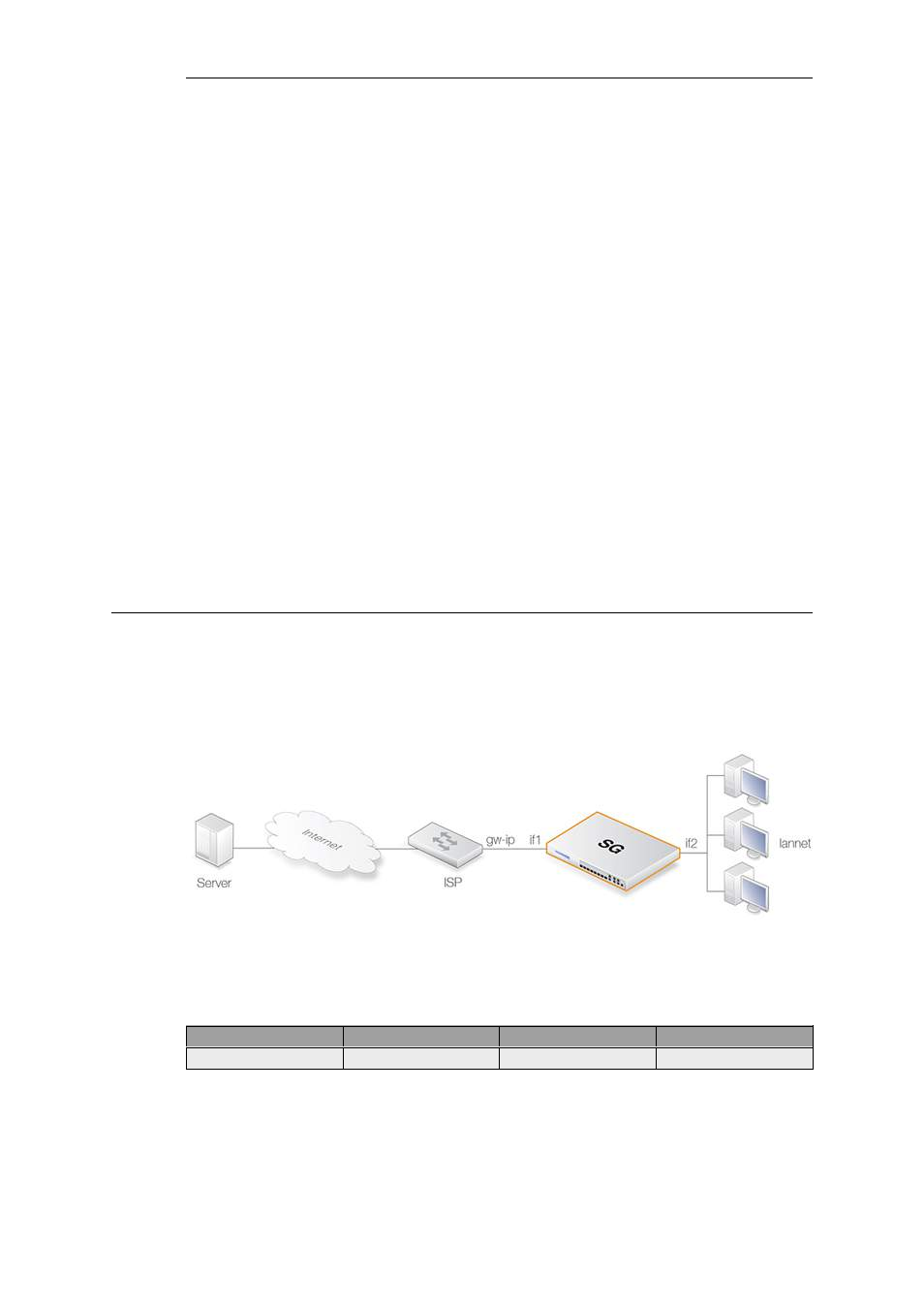
access to the public Internet. Below is a typical scenario where a number of users on an IP
network called lannet access the Internet via an ISP's gateway with IP address gw-ip.
Figure 4.24. Non-transparent Mode Internet Access
The non-switch route usually needed to allow Internet access would be:
Route type
Interface
Destination
Gateway
Non-switch
if1
all-nets
gw-ip
Now lets suppose the Clavister Security Gateway is to operate in transparent mode between the
users and the ISP. The illustration below shows how, using switch routes, the Clavister Security
Gateway is set up to be transparent between the internal physical Ethernet network (pn2) and
the Ethernet network to the ISP's gateway (pn1). The two Ethernet networks are treated as a
Chapter 4: Routing
345