Comtech EF Data C5 User Manual
Page 272

Options
C5/K1/K3 Integrated Satellite Terminal System
A–28
Rev. 0
PLL
DDS
TXD
TXC
EXT
REF
INT
RXC
S2
S1
MC
ST
TT
TXD
S4
S3
OUTPUT
Clock Selection
S1 set to:
S2 set to:
S3 set to:
S4 set to:
TX TERR (TT)
DDS
INT
TT
INT (SCT)
DDS
INT
ST
SCT (INT)
DDS
EXT REF
(See Note 2)
ST
SCT (LOOP)
DDS
EXT REF
(See Note 2)
ST
INT (LOOP)
(See Note 1)
RXC
PLL
ST
EXT CLOCK
MC
PLL
ST
Notes:
1. When CONFIGURATION INTERFACE # LOOP TIMING is set to ON,
SCT (INT) will change to read: SCT (LOOP).
2. When CONFIGURATION MOD # MOD REF is set to EXT MOD, S3 will
switch to the EXT REF position.
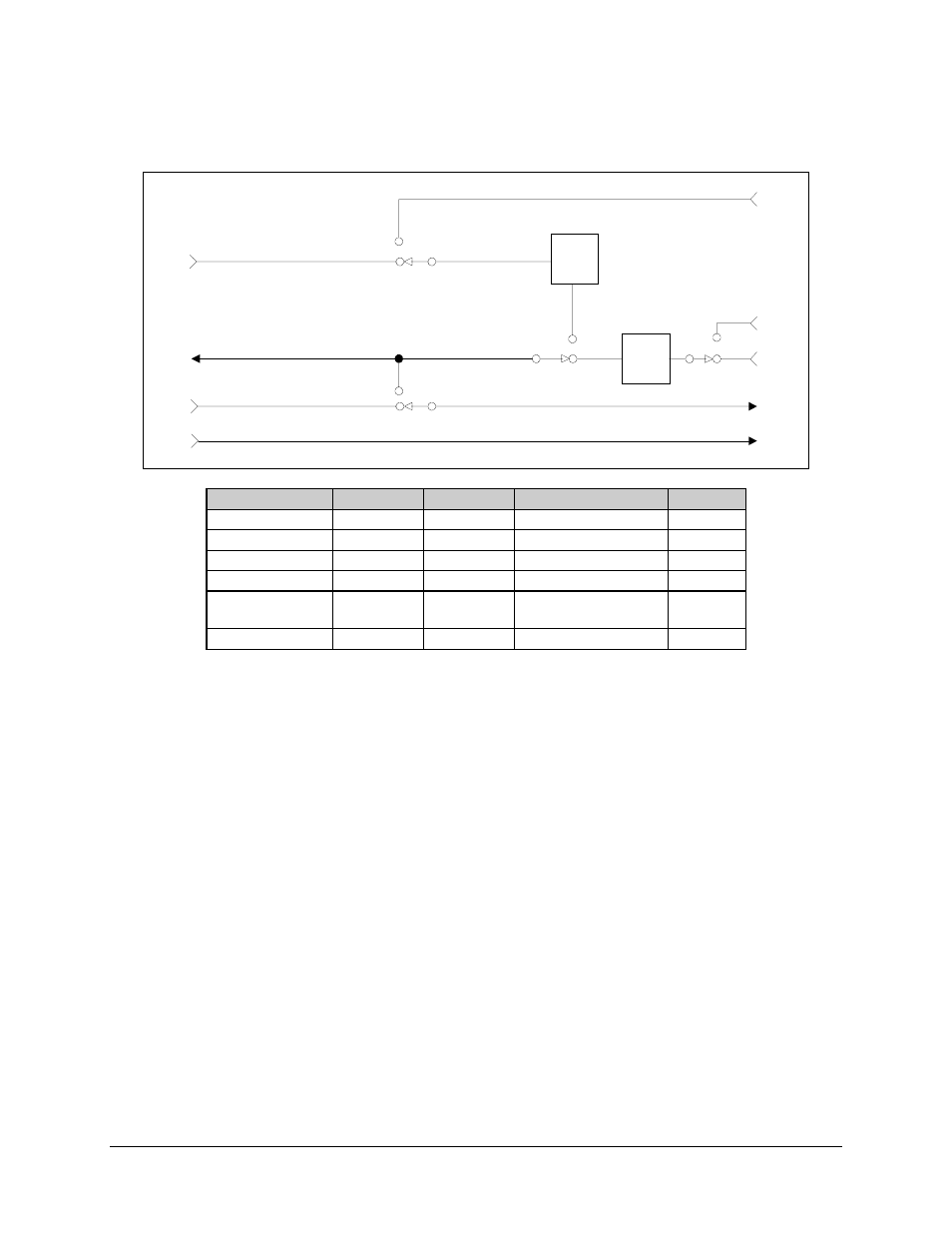
Figure A-6. Transmit Section of the Asymmetrical Loop Timing Block Diagram
