Table a-4 – Comtech EF Data C5 User Manual
Page 262
Options
C5/K1/K3 Integrated Satellite Terminal System
A–18
Rev. 0
A.2.1.5.2
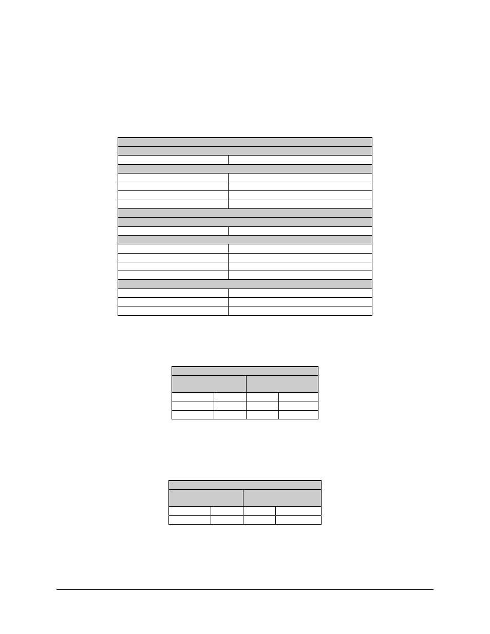
Configuration #2 (Local EIA-232 to Remote EIA-485 [2-Wire])
Table A-4. Local EIA-232 to Remote EIA-485 (2-Wire)
#3. Local End Modem Settings for EIA-232
Utility Interface Menu
ASYNC TX and RX Type
EIA-232
Configuration Interface Menu
ASYNC TX and RX Baud Rate
150 to 38400
(See A.1.4.3.10)
ASYNC TX and RX Length
7 bits
ASYNC TX and RX Parity
Even
ASYNC TX Stop
2 bits
#3. Remote End Modem Settings for EIA-485 (2-Wire)
Utility Interface Menu
ASYNC TX and RX Type
EIA-485 (2-wire)
Configuration Interface Menu
ASYNC TX and RX Baud Rate
150 to 38400
(See A.1.4.3.10)
ASYNC TX and RX Length
7 bits
ASYNC TX and RX Parity
Even
ASYNC TX Stop
2 bits
Utility System Menu
Remote Baud Rate
Equal to ASYNC TX and RX baud rate
Parity
Even
Address
1 to 255
The local end cable connects the 25-pin female ASYNC connector (on either the
breakout panel or the Y cable) to the EIA-232 remote terminal (WYSE or laptop
computer). The pinout of the local cable is listed in the following table.
#3. Local End EIA-232
9-Pin
Female Connector
25-Pin
Male Connector
RX
2
3
TX
TX
3
2
RX
GND
5
7
GND
The remote end cable connects the 25-pin female ASYNC connector (on either the
breakout panel or the Y cable) to the 9-pin female connector, J6, at the rear of the
modem. The pinout of the remote cable is listed in the following table.
#3. Remote End EIA-485 (2-Wire)
9-Pin
Male Connector
25-Pin
Male Connector
TX/RX+
4
14, 16
TX+, RX+
TX/RX-
5
2, 3
TX-, RX-