Comtech EF Data C5 User Manual
Page 213

C5/K1/K3 Integrated Satellite Terminal System
Theory of Operation
Rev. 0
5-3
MODEM
11 MHz
CLOCK
I C BUS
2
RAM AND
REAL
TIME
CLOCK
ROM
(M&C,
BULK,
BOOT)
FAULT
AND ALARM
RELAYS
MICRO-
CONTROLLER
DAC
ADC
UART
EIA-232
OR
EIA-485
9-PIN
REMOTE
ASK
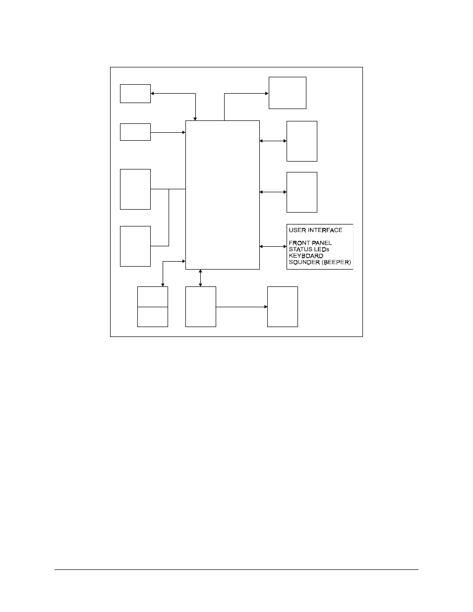
Figure 5-1. M&C Block Diagram
The heart of the M&C card is the Dallas
" 80C310 microcontroller operating at 11 MHz.
This Microcontroller contains 256 kbit/s of internal RAM. The external ROM is 29F040
(512 kbit/s).
ROM access times must be equal to or greater than 150 ns. The RAM can be 8 kbit/s or 32
kbit/s in size. This RAM chip is internally battery-backed and contains a real time clock
used by the M&C.
