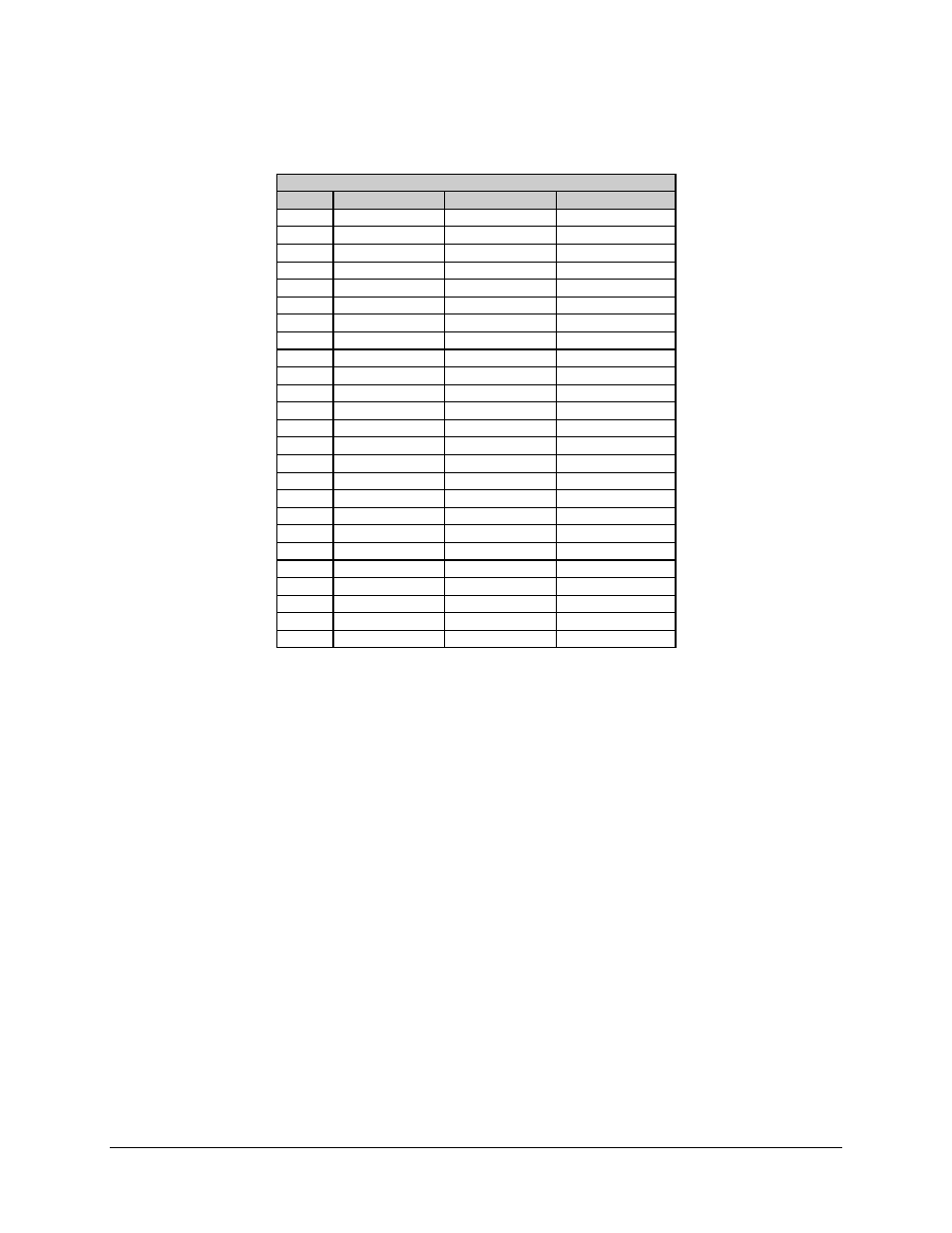
Table 3-4 – Comtech EF Data C5 User Manual
Page 116

Installation
C5/K1/K3 Integrated Satellite Terminal System
3–20
Rev. 0
Table 3-4. 25-Pin D Connector Pinouts
25-Pin D Connector
Pin #
EIA-422
EIA-232
V.35
1
SHLD
SHLD
SHLD
2
SD-A
TXD
SD-A
3
RD-A
RXD
RD-A
4
RS-A
RTS
RTS
5
CS-A
CTS
CTS
6
DM-A
DSR
DSR
7
SIGGND
SIGGND
SIGGND
8
RR-A
DCD
RLSD
9
RT-B
SCR-B
10
RR-B
11
TT-B
SCT-B
12
ST-B
SCTE-B
13
CS-B
14
SD-B
SD-B
15
ST-A
ST
SCTE-A
16
RD-B
RD-B
17
RT-A
RXC
SCR-A
18
LL
LL
LL
19
RS-B
20*
MC-A
MC
MC-A
21
DF
DF
DF
22
DM-B
23*
MC-B
MC-B
24
TT-A
TXC
SCT-A
25
MF
MF
MF
*Note: Use the MASTER clock for EXTERNAL clock input. This clock input
should equal the data rate unless the Asymmetrical Loop Timing Option (ASLT)
is available. The ASLT option allows selection of different clock rates that vary
from the digital data rate. Refer to the Utility/Modem Type/Modem Options
menu for the ASLT option information.
