Comtech EF Data C5 User Manual
Page 22
Introduction
C5/K1/K3 Integrated Satellite Terminal System
1–2
Rev. 0
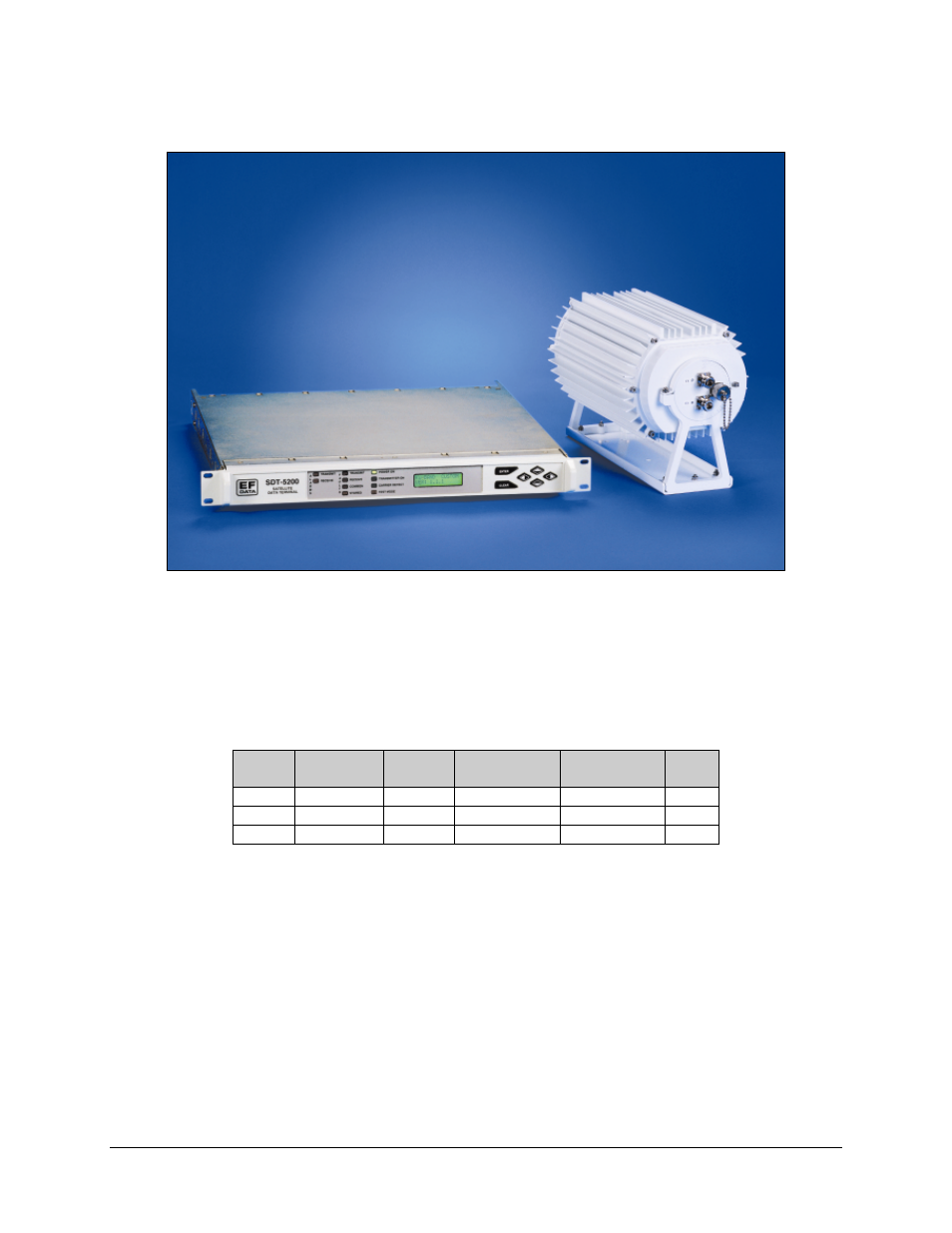
Figure 1-2. The Ku-Band (K1 or K3) System
Refer to Table 1-1 for a matrix of customer-selectable configured units.
Table 1-1. Customer-Selectable Configured Units
ODU
ODU
ODU
System
IDU
C-Band
Ku-Band 1W
Ku-Band 3W
LNA
C5
SDT-5200
X
X
K1
SDT-5200
X
K3
SDT-5200
X
C-Band System - A block diagram (Figure 1-3) illustrates the system as a single thread,
single channel per carrier per carrier (SCPC), very small aperture terminal (VSAT)
consisting of a full featured modem, an up converter/transceiver, and a low-noise
amplifier (LNA) designed to meet the needs of single and/or multiple site installations.
Ku-Band System - A block diagram (Figure 1-4) illustrates the system as a single
thread, single channel per carrier per carrier (SCPC), and very small aperture terminal
(VSAT) consisting of a full featured modem and an up converter/transceiver.
The outdoor unit (ODU) is a weatherproof enclosure housing the up converter, solid-
state power amplifier, automatic level control, block down converter, IF interfaces,
monitor and control (M&C), and a DC power converter.