Local end remote end – Comtech EF Data C5 User Manual
Page 259
C5/K1/K3 Integrated Satellite Terminal System
Options
Rev. 0
A–15
Before remote ASYNC communications can be implemented, the following must occur:
! At both the local and remote modems, front panel configuration parameters must
be set for each type of configuration.
! Industry-standard cables must be used at both modems.
To implement remote ASYNC operation, use the configuration information found in the
applicable section and perform the following steps:
1. Set the jumpers on the remote modem M&C/Display PCB according to the
information found in the applicable configuration section.
2. Set the local modem front panel controls according to the information found in
the applicable configuration section.
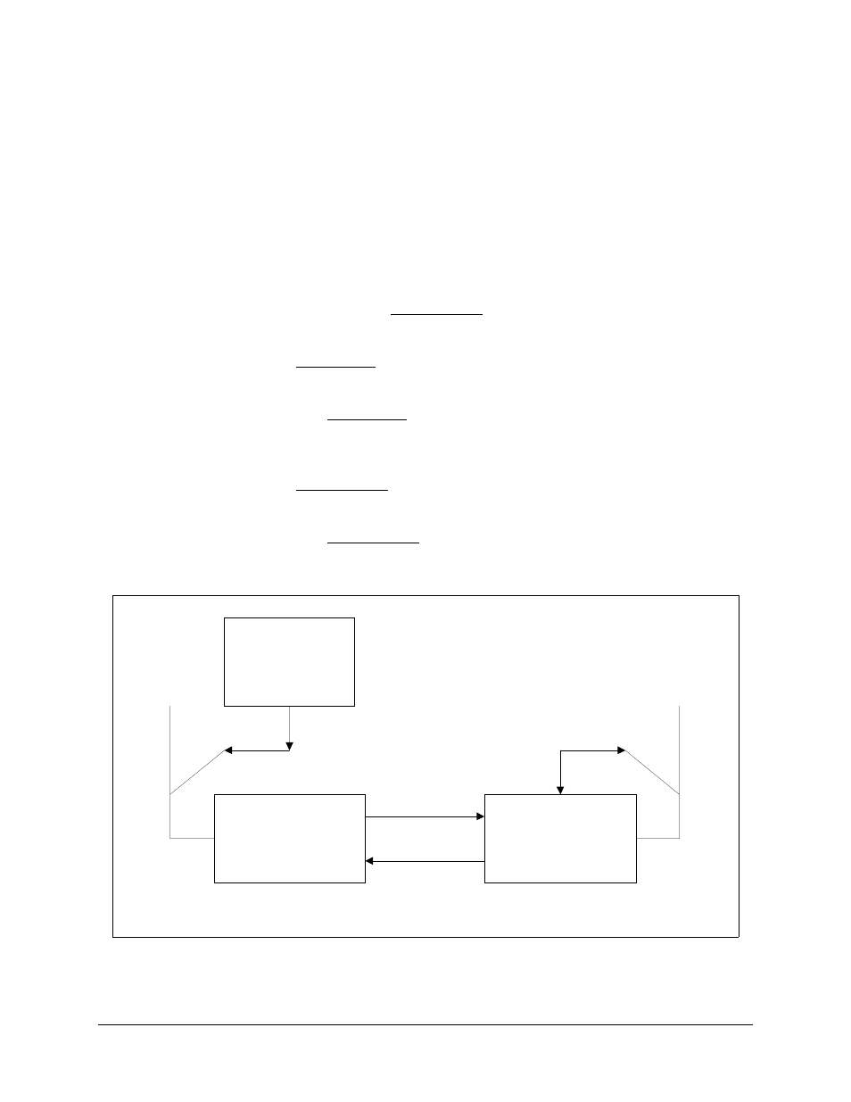
3. Connect the local modem 25-pin ASYNC connection (via breakout panel or Y
cable) to the terminal using the pinout information found in the applicable
configuration section. Refer to Figure A-2.
4. Set the remote modem front panel controls according to the information found in
the applicable configuration section.
5. Connect the remote modem 25-pin ASYNC connection (via breakout panel or Y
cable) to the 9-pin J6 port at the rear of the modem using the pinout information
found in the applicable configuration section. Refer to Figure A-3.
WYSE
REMOTE TERMINAL
(OR EQUIVALENT)
ASYNC INTERFACE
ASYNC INTERFACE
V.35
DATA
CONNECTOR
25-PIN
ASYNC
CONNECTOR
REMOTE EIA-485
(4-WIRE)
CABLE
(9-PIN TO 25-PIN)
J8
J6
TX -30 dBm
RX
RX
TX -30 dBm
J8
V.35
DATA
CONNECTOR
25-PIN
ASYNC
CONNECTOR
LOCAL EIA-485
(4-WIRE)
CABLE
(9-PIN TO 25-PIN)
EIA-485
25-PIN CONNECTOR
TO
9-PIN CONNECTOR
(INDUSTRY STANDARD)
CA/4056
CA/4056
LOCAL END
REMOTE END
BENCH TEST
50-PIN
50-PIN
Figure A-2. Remote ASYNC Connection Diagram for Y Cable