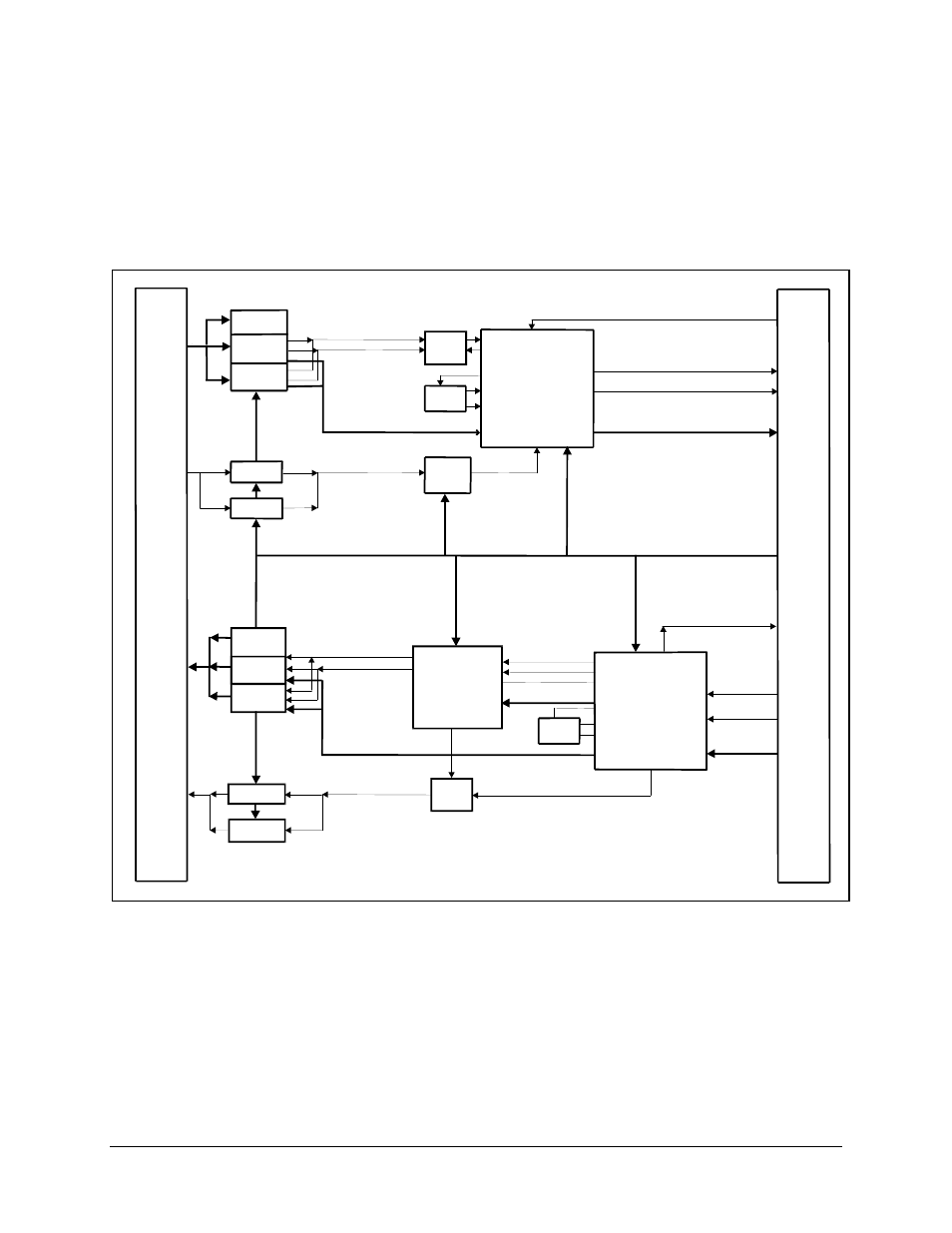
Figure a-1. async/aupc block diagram – Comtech EF Data C5 User Manual
Page 251

C5/K1/K3 Integrated Satellite Terminal System
Options
Rev. 0
A–7
The ASYNC interface PCB also provides its own Doppler buffer, which has a maximum
depth of 32 ms at the highest terrestrial data rate. Buffer fill status can be checked in the
Monitor menu on the front panel of the modem. Depth selection and centering of the
buffer are provided in the Configuration Interface menu.
G.703
RS-422
V.35
TERR DATA
TERR CLOCK
INPUT
FIFO
PLL
INTERFACE CNT SIGNALS
AUPC DATA FROM M&C
TERR DATA
TERR OVERHEAD CLOCK
INTERFACE CNT SIGNALS
ASYNC DATA
ASYNC DATA
UART
RS-485
RS-232
M&C CONTROL
G.703
RS-422
V.35
TERR DATA
TERR CLOCK
BUFFER
AUPC DATA TO M&C
RX DATA
RX CLK
INTERFACE
SIGNALS
PLL
UART
ASYNC DATA
INTERFACE SIGNAL
RS-485
RS-232
DMUX
TERR DATA
RX CLK
ENABLE
4 OUTPUT
CLK SOURCES
MUX
M
O
D
U
L
A
T
O
R
D
E
M
O
D
U
L
A
T
O
R
T
E
R
R
E
S
T
R
I
A
L
Figure A-1. ASYNC/AUPC Block Diagram
