Comtech EF Data C5 User Manual
Page 264
Options
C5/K1/K3 Integrated Satellite Terminal System
A–20
Rev. 0
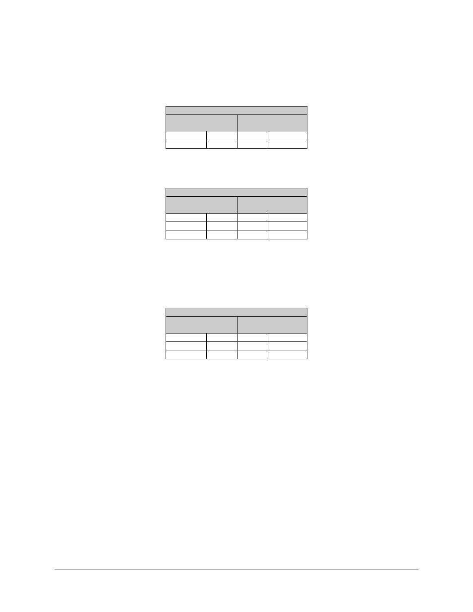
The local end cable connects the 25-pin female ASYNC connector (on either the
breakout panel or the Y cable) to the EIA-485 (2-wire) remote terminal (WYSE or laptop
computer). The pinout of the local cable is listed in the following table.
#7. Local End EIA-485 (2-Wire)
9-Pin
Female Connector
25-Pin
Male Connector
TX/RX+
4
14, 16
TX+/RX+
TX/RX-
5
2, 3
TX-/RX-
In addition, the following table lists the pinout for the WYSE terminal cable using an
EIA-232 to EIA-485 converter.
#7. Local End WYSE Cable With Converter
25-Pin
Male Connector
9-Pin
Male Connector
TX-/RX-
2, 5
5
TX/RX-
TX+/RX+
14, 17
4
TX/RX+
(See Note)
18, 21
Note: Disables RD during TD.
The remote end cable connects the 25-pin female ASYNC connector (on either the
breakout panel or the Y cable) to the 9-pin female connector, J6, at the rear of the
modem. The pinout of the remote cable is listed in the following table.
#7. Remote End EIA-232
9-Pin
Male Connector
25-Pin
Male Connector
RX
2
2
RX
TX
3
3
TX
GND
5
7
GND